1. For the half-wave rectifier circuit of Figure 2–1A, the peak load voltage is approximately :(a) 6 V ¯.. 2. For an input frequency of 60 Hz, the period of the half-wave signal is approximately (a) 4 ms 3. Compared to the de output voltage of the half-wave rectifier of Figure 2-1A, the de output voltage of the full-wave bridge rectifier of Figure 2-1C is approximately (a) one-half as large 4. In this experiment, the rectifier circuit that has the lowest diode peak inverse voltage is the (a) half-wave rectifier (c) full-wave bridge rectifier (d) both a and c 5. In this experiment, the rectifier circuit that has the greatest de output voltage is the (a) half-wave rectifier (c) full-wave bridge rectifier (b) 12 V (c) 18 V - (d) 24 V (b) 8 ms (c) 16 ms (d) 32 ms (b) the same (c) twice as large ( ) (b) full-wave center-tapped rectifier ( ) (b) full-wave center-tapped rectifier TUIC ALL C ICUD r vO INEE D.
1. For the half-wave rectifier circuit of Figure 2–1A, the peak load voltage is approximately :(a) 6 V ¯.. 2. For an input frequency of 60 Hz, the period of the half-wave signal is approximately (a) 4 ms 3. Compared to the de output voltage of the half-wave rectifier of Figure 2-1A, the de output voltage of the full-wave bridge rectifier of Figure 2-1C is approximately (a) one-half as large 4. In this experiment, the rectifier circuit that has the lowest diode peak inverse voltage is the (a) half-wave rectifier (c) full-wave bridge rectifier (d) both a and c 5. In this experiment, the rectifier circuit that has the greatest de output voltage is the (a) half-wave rectifier (c) full-wave bridge rectifier (b) 12 V (c) 18 V - (d) 24 V (b) 8 ms (c) 16 ms (d) 32 ms (b) the same (c) twice as large ( ) (b) full-wave center-tapped rectifier ( ) (b) full-wave center-tapped rectifier TUIC ALL C ICUD r vO INEE D.

Electricity for Refrigeration, Heating, and Air Conditioning (MindTap Course List)
10th Edition
ISBN:9781337399128
Author:Russell E. Smith
Publisher:Russell E. Smith
Chapter12: Electronic Control Devices
Section: Chapter Questions
Problem 4RQ: What is the difference between a diode and rectifier?

Related questions

Question
100%
This multiple choice questions from electronics lab,please solve all,it easy for you and good luck in your life.
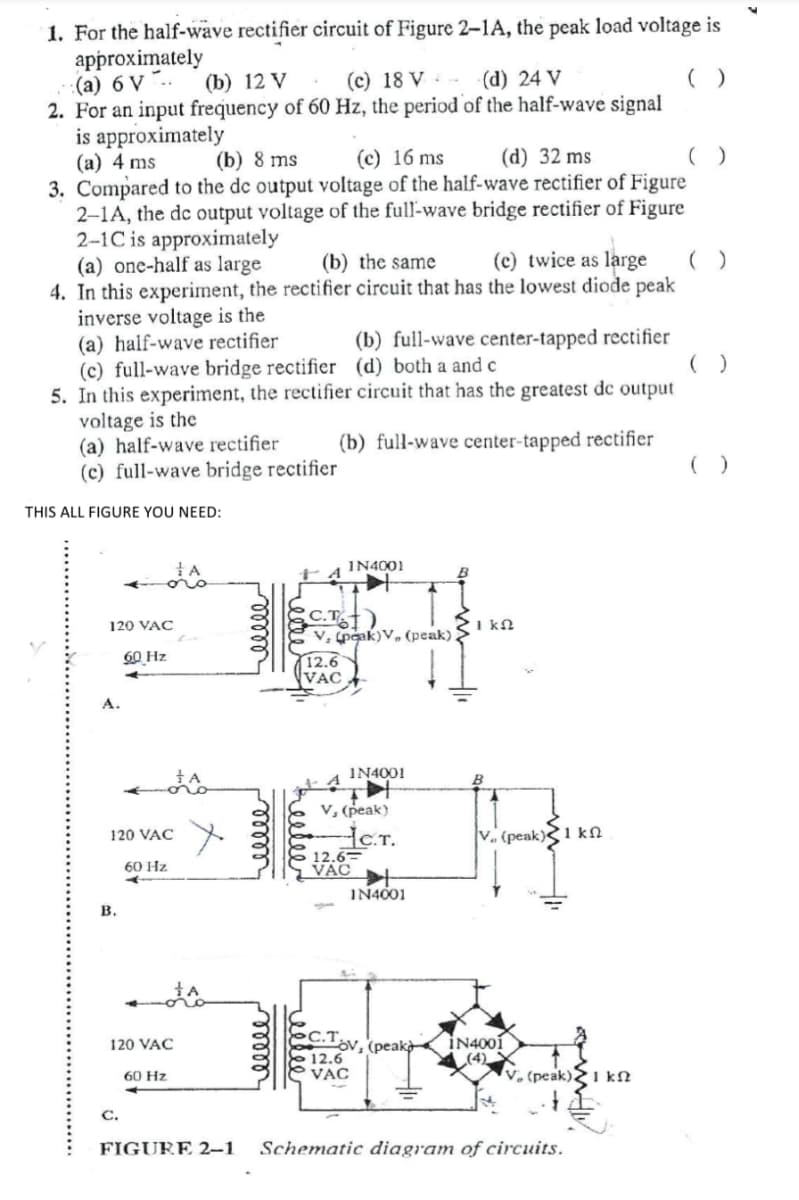
Transcribed Image Text:1. For the half-wave rectifier circuit of Figure 2–1A, the peak load voltage is
approximately
(а) 6 V "..
2. For an input frequency of 60 Hz, the period of the half-wave signal
is approximately
(а) 4 ms
3. Compared to the de output voltage of the half-wave rectifier of Figure
2-1A, the dc output voltage of the full-wave bridge rectifier of Figure
2-1C is approximately
(a) one-half as large
4. In this experiment, the rectifier circuit that has the lowest diode peak
inverse voltage is the
(a) half-wave rectifier
(c) full-wave bridge rectifier (d) both a and c
5. In this experiment, the rectifier circuit that has the greatest de output
voltage is the
(a) half-wave rectifier
(c) full-wave bridge rectifier
(b) 12 V
(c) 18 V -
(d) 24 V
()
(b) 8 ms
(c) 16 ms
(d) 32 ms
(b) the same
(c) twice as large
(b) full-wave center-tapped rectifier
(b) full-wave center-tapped rectifier
( )
THIS ALL FIGURE YOU NEED:
IN4001
C.T
v, peak)V, (peak) >
120 VAC
I kN
60 Hz
12.6
VAC
А.
IN4001
V, (peak).
.T.
12.6=
VAC
120 VAC
V. (peak)1 kN
60 Hz
IN4001
в.
C.T v, (peakà
İN4001
(4)
V, (peak)21 kN
120 VAC
12.6
VAC
60 Hz
С.
FIGURE 2–1
Schematic diagram of circuits.
Expert Solution
This question has been solved!
Explore an expertly crafted, step-by-step solution for a thorough understanding of key concepts.

This is a popular solution!

Trending now
This is a popular solution!

Step by step
Solved in 2 steps with 2 images

Knowledge Booster


Learn more about
Need a deep-dive on the concept behind this application? Look no further. Learn more about this topic, electrical-engineering and related others by exploring similar questions and additional content below.Recommended textbooks for you
Electricity for Refrigeration, Heating, and Air C…
Mechanical Engineering
ISBN:
9781337399128
Author:
Russell E. Smith
Publisher:
Cengage Learning
Electricity for Refrigeration, Heating, and Air C…
Mechanical Engineering
ISBN:
9781337399128
Author:
Russell E. Smith
Publisher:
Cengage Learning