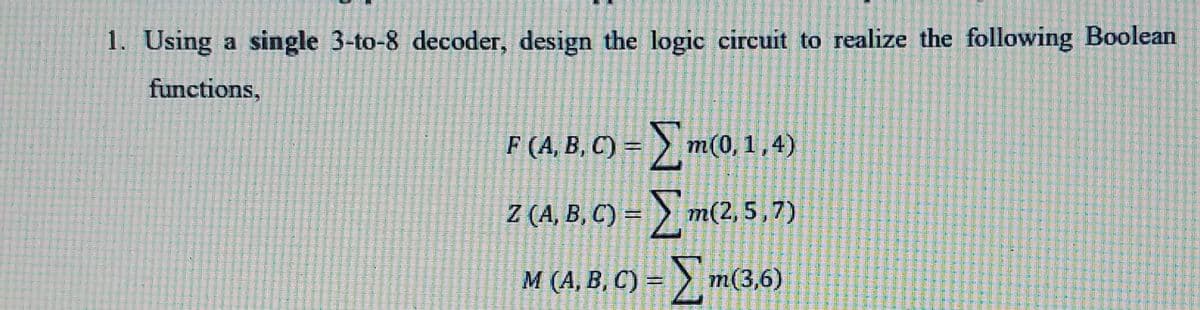
1. Using a single 3-to-8 decoder, design the logic circuit to realize the following Boolean functions, F (A, B, C) = > m(0, 1 ,4) Z (A, B, C) = > m(2, 5,7) Σ M (A, B, C) =


Q: Q. Use the below PAL device to realize the logic functions f,and f2 given by the following truth…
A: Given here a truth table asked to implement the PAL functionality. here x, y, z are the inputs and…
Q: 3.) Logic Function F(x,y,z,w) =∑ m(0,2,4,6,8,13) + ∑ k(10,12) is given as the sum of miniterms.…
A:
Q: (a) From the expression X = ( (X+Y* +Z)* +XYZ*)*+Z) where * indicates the complement %3D (1) Draw…
A: As per the guidelines, we supposed to answer one question at a time so please ask other questions…
Q: (a) Simplify the following Boolean expression 'A' and draw the logic diagram for the simplified…
A:
Q: 10 11 12 13 A C 4X1 Q MUX F(A,B,C,D) S1 SO A = MSB D = LSB в D Which of the following is the writing…
A:
Q: Design a circuit such that it compares the magnitude of two 1-bit numbers and gives an output,…
A: Comparator- A comparator is a logic circuit used to compare the magnitude of two binary numbers.It…
Q: ) Logic Function F (x, y, z, w) = ∑ m (0,2,4,6,10,13) + ∑ k (8,12) as sum of minimers is given a)…
A:
Q: 1. The expression F (A, B, C) = E (0,2,5,6,7) a. Draw the truth table b. Generate the Karnough map…
A:
Q: 8. Given f(w, x, y, z) = II(0, 1, 3,5, 13), a) Write the complete truth table for Y = f(w, x, y, z).…
A: Dear student as per our guidelines we are supposed to solve only one question in which it should…
Q: 2) Design a logic circuit to realize the following Boolean function F(x,y,z) = IIM(0,1, 2, 6, 7) D)…
A: 1.Decoder
Q: Q.3/ Using a decoder and external gates, design the combinational logic circuit defined by the…
A:
Q: TABLE 1 INPUTS OUTPUT QR S Y 1 1 1 1 1 1 1 1 1 1 1 1 1 1 1 1 1 1 1 1 1 1 1 1 1 1 1 1 1 1 1 1 1 1 1 1…
A:
Q: (a) From the expression X = ( (XY*Z+(XY)*)*+XYZ ) where '*' indicates the complement (i) Draw the…
A:
Q: 1a. Design a logic circuit that implements an expression that equals 1 (output) when exactly two of…
A: As per our guidelines, we are supposed to answer only one question or 3 Subparts. Kindly repost…
Q: Dynamic RAM are constructed using Latches. ( True / False ) In an SR Latch, if S = 0 and R=1, the…
A: Dram is made up of transistor and capacitor. When S=0 ,R= 1 output is Reset And gate perform…
Q: 3. Design the logic function whose truth table is given below using PROM B Output(F) 1 1 1 1 1 1 1 1…
A: Given: Truth table: Inputs: A,B,C Output: F
Q: implified using S.O.P., then draw logic circuit for your Boolean expression. y(A, B, C, D) Σ1,10,14)…
A: First we will find the simplified expression then we will draw the circuit.
Q: B/ Write a Boolean expression for this truth table, then simplify that expression as much as…
A: Given Truth Table: A B C output 0 0 0 1 0 0 1 1 0 1 0 0 0 1 1 1 1 0 0 0 1 0 1 1 1 1…
Q: Minimize the following expression applying K-map: A(B' CD + B' C') +AC+ A' C D' 3. Make a Full…
A: K-map is used to minimize the expression. It is represented as a table of rows or columns having…
Q: Derive the hazard free Boolean expression for given logic function.…
A: The given expression is in the SOP (sum of products) form. 0 - 0000 4 - 0100 5 - 0101 10 - 1010 11 -…
Q: Q. Use the below PAL device to realize the logic functions f1and f2 given by the following truth…
A: The solution is given below
Q: A logic family has a power-delay product of 100 fJ.If a logic gate consumes a power of 100 W,…
A: Given: PDP= 100 fJP= 100 μW
Q: Minimize the following Equation by using Karnaugh Map, then draw the final Logic Circuit of the…
A:
Q: 1-Convert the following logic ladder to a Boolean equation. Then simplify it. Draw the electric…
A: The idea is, when two logics are in parallel, it gets added and when in series gets multiplied. 1.…
Q: (b) Given the Boolean expression, m = (x + y)(y + z)(x +y)(y+ z) Construct a truth table for the…
A:
Q: Design a 4-bit even-parity detector (3 data bits and 1 parity bit) 1. Draw the block diagram of the…
A: Here we need to fill the truth table for a 4-bit even-parity detector. The output is 1 if the parity…
Q: 11. Given the table below, write the (a) simplify the disjunctive normal form, justifying each step…
A: The boolean algebra involves the operations applied on boolean variables. The boolean variables have…
Q: 1. Draw a logic diagram based on the Boolean expression below, using bus form: Y = (ABC) + (B + C)…
A:
Q: 4. The truth table of a logic operation is given at the right- hand side. A В C Y 1 (a) Derive the…
A:
Q: truth table, then simplify that expression as much as possible, and draw a logic gate circuit…
A: we need solve K map to get the simplified solution and then the logic gate circuit.
Q: Q. 2 Using an 4-to-1 multiplexer, design a logic circuit to realize the following Boolean function,…
A: Disclaimer: Since you have asked multiple questions, we will solve the first question for you. If…
Q: A + B = AB a. Using truth tables for both the right and left sides of the equation. b. Drawing a…
A: As per the guidelines of Bartleby we have to solve first three sub part of the question for…
Q: A Boolean function using the three variables function, given by F(A,B,C) = ac' + a'c is implemented…
A: Given F(A, B, C) = ac'+a'c
Q: Question 2 A truth table indicating the state of an output, Z, as it depends on three inputs A, B…
A:
Q: 3. Design a PLA circuit which realizes the following Boolean functions: (a) Simplify the Boolean…
A:
Q: (a) Draw the digital circuit to implement the following expressions: (i) (A.B).(B.C).(CD) (ii)…
A:
Q: 2) Simplified using S.O.P., then draw logic circuit for your Boolean expression. y(A, B,C,D) =…
A:
Q: Design a simple circuit from the function Y by reducing it using appropriate k-map , draw…
A: Given truth table of the function Y
Q: For the function F = AB’C’+ AB, find the logic value of F under the conditions— (a) A = 0, B = 1, C…
A: Given F = AB'C' + AB Find the output for the given input combinations A. 011 B. 100 C. 101 D.…
Q: Using Karnaugh map, simplify the expression F(W, X, Y, Z) = Σm(0, 1, 2, 4, 5, 6, 8, 9, 12, 13, 14).…
A:
Q: (b) Given the Boolean expression, m = (x + y)(y + z)(x + ỹ)(ỹ +z) (ii) Derive the minimal sum of…
A:
Q: Task 3: Digital logic circuit analysis - Finding the Boolean expression of a given circuit Find the…
A: Redrawing the circuit by applying the input as shown below:
Q: (a) Write the Truth Table for the Boolean expression X = m (0, 2, 3, 4, 5) Write the POS expression…
A: NAND GATE Y = (AB)° In this question we have used this symbol ° = COMPLEMENT OR BAR POS =…
Q: Given f (w, x, y, z) = II(0, 1,3, 5, 13), a) Write the complete truth table for Y = f(w, x, y, z).…
A:
Q: In this exercise, you will be creating a 4-variable K-map to minimize the logic for the truth table…
A:
Q: Q. If the the given Boolean Function, F(A, B, C, D) = E(1,4, 8, 9, 10, 11, 12, 14). is reduced using…
A: The SOP form is a method of simplifying the Boolean expressions of logic gates. In this SOP form of…
Q: Procedure: 1. Connect the logic circuit required to implement the function F in equation below and…
A: The logic circuit can be drawn by using the basic gates and the truth table can be obtained by…
Q: Given the Logic Circuit above, fill-up the truth table below.
A: NAND GATE A B Output 0 0 1 0 1 1 1 0 1 1 1 0 EXOR GATE A B Output 0 0 0 0 1…
Q: 1. Design a circuit that produces 1 if a 2-bits binary number is odd, otherwise the circuit produces…
A: We are authorized to answer one question at a time, since you have not mentioned which question you…

Step by step
Solved in 2 steps with 2 images


- (2) Design synchronous mod 5 counter State table, K-map, boolean equations, and logic circuit. (coding not needed) (Please do not write by hand.)Logic Function F (x, y, z, w) = ∑ m (0,2,4,6,10,13) + ∑ k (8,12) as sum of minimers are given. (Note: There are terms that are not taken into account.) a. Obtain the Truth Table. b. Simplify with the Karnough Map approach. c. Draw the simplified Logic circuit with two input AND-NOT (NAND) gates. How many elements you realized, what is your gain? Comment.3.) Logic Function F(x,y,z,w) =∑ m(0,2,4,6,8,13) + ∑ k(10,12) is given as the sum of miniterms. (Note: There are terms that are ignored.) a. Obtain the Truth Table. b. Simplify with the Karnough Map approach. NS. Implement the simplified Logic circuit with only two-input AND-NOT (NAND) gates. How many apples did you use, please comment.
- 3) Logic Function F (x, y, z, w) = ∑ m (0,2,4,6,10,13) + ∑ k (8,12) as sum of minimers is given a) Obtain the Truth Table. b) Simplify with the Karnough Map approach. c) Draw the simplified Logic circuit with two input AND-NOT (NAND) gates. With how many apples you realized, what is your gain? Comment.Q1. Design a simple circuit from the function Y by reducing it using appropriate k-map , draw corresponding Logic Diagram for the simplified Expression Truth Table D C B A Y 0 0 0 0 0 0 1 0 0 0 1 1 2 0 0 1 0 1 3 0 0 1 1 0 4 0 1 0 0 1 5 0 1 0 1 0 6 0 1 1 0 0 7 0 1 1 1 1 8 1 0 0 0 1 9 1 0 0 1 0 10 1 0 1 0 0 11 1 0 1 1 1 12 1 1 0 0 0 13 1 1 0 1 1 14 1 1 1 0 1 15 1 1 1 1 0 #Implement the simplified logical expression of Question 1 using universal gates (NAND) How many NAND gates are required as well specify how many ICs are neededDesign a Combinational circuit with a Decoder to accept 3-bit number and generate the output binary number equal to the Square of the input number.a) Derive the truth table.b) Find simplified output function in Product of Sum(POS).c) Draw the logic diagram in logisim Simulator.
- A combinational circuit with three inputs (A, B and C) generates the 2’s complement of the input binary number as output (Note: The number of output bits may be one more than input bits). (a) Obtain the truth table (Take output as W, X, Y, Z). (b) Obtain the simplified output function in sum of products form. (c) Draw the logic diagram for simplified output function. (d) Design the circuit using decoder also.2. Simplify F(x, y, z) = summation(2, 3, 4, 6, 7) d(x, y, z) = summation (1, 5) and Draw an all-NAND logic diagram for the simplified function in #2.For the given function P P (A, B, C, D) =∑m (0,1,2,4,6,7,8,9,10,11,12) + d (3,13,15) a. Simplify P using K-Map b. Draw logic diagram for simplified function
- (1)Why the input lines of the MUX do not appear in the truth table with its logic values?Draw a block diagram, truth table and logic circuit of 1*16 Demultiplexer and explain its working principle.Design a combinational logic circuit that converts a three-bit binary number from code A to code B, according to the table on the right. Answer the following questions: Code A Code B 000 000 001 001 011 010 010 011 110 100 111 101 101 110 100 111 Construct the truth table for the circuit.