10. From memory, sketch the transistor symbol for a pnp and an npn transistor, and then insert the conventional flow direction for each current.
10. From memory, sketch the transistor symbol for a pnp and an npn transistor, and then insert the conventional flow direction for each current.

Introductory Circuit Analysis (13th Edition)
13th Edition
ISBN:9780133923605
Author:Robert L. Boylestad
Publisher:Robert L. Boylestad
Chapter1: Introduction
Section: Chapter Questions
Problem 1P: Visit your local library (at school or home) and describe the extent to which it provides literature...

Related questions

Question
Answer 10 only. Show the process
Transcribed Image Text:PROBLEMS
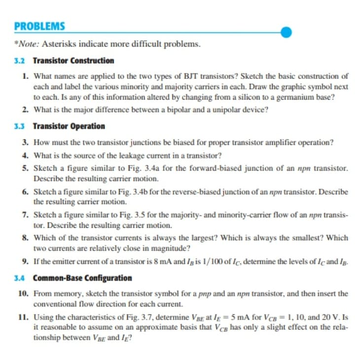
*Note: Asterisks indicate more difficult problems.
3.2 Transistor Construction
1. What names are applied to the two types of BJT transistors? Sketch the basic construction of
each and label the various minority and majority carriers in each. Draw the graphic symbol next
to each. Is any of this information altered by changing from a silicon to a germanium base?
2. What is the major difference between a bipolar and a unipolar device?
3.3 Transistor Operation
3. How must the two transistor junctions be biased for proper transistor amplifier operation?
4. What is the source of the leakage current in a transistor?
5. Sketch a figure similar to Fig. 3.4a for the forward-biased junction of an npn transistor.
Describe the resulting carrier motion.
6. Sketch a figure similar to Fig. 3.4b for the reverse-biased junction of an npn transistor. Describe
the resulting carrier motion.
7. Sketch a figure similar to Fig. 3.5 for the majority- and minority-carrier flow of an npn transis-
tor. Describe the resulting carrier motion.
8. Which of the transistor currents is always the largest? Which is always the smallest? Which
two currents are relatively close in magnitude?
9. If the emitter current of a transistor is 8 mA and Ig is 1/100 of Ic, determine the levels of Iç and Ig.
3.4 Common-Base Configuration
10. From memory, sketch the transistor symbol for a pnp and an npn transistor, and then insert the
conventional flow direction for each current.
11. Using the characteristics of Fig. 3.7, determine VBE at Ig = 5 mA for VcB = 1, 10, and 20 V. Is
it reasonable to assume on an approximate basis that Vcg has only a slight effect on the rela-
tionship between VBE and Ig?
Expert Solution
This question has been solved!
Explore an expertly crafted, step-by-step solution for a thorough understanding of key concepts.

This is a popular solution!

Trending now
This is a popular solution!

Step by step
Solved in 2 steps with 1 images

Knowledge Booster


Learn more about
Need a deep-dive on the concept behind this application? Look no further. Learn more about this topic, electrical-engineering and related others by exploring similar questions and additional content below.Recommended textbooks for you
Introductory Circuit Analysis (13th Edition)
Electrical Engineering
ISBN:
9780133923605
Author:
Robert L. Boylestad
Publisher:
PEARSON

Delmar's Standard Textbook Of Electricity
Electrical Engineering
ISBN:
9781337900348
Author:
Stephen L. Herman
Publisher:
Cengage Learning

Programmable Logic Controllers
Electrical Engineering
ISBN:
9780073373843
Author:
Frank D. Petruzella
Publisher:
McGraw-Hill Education
Introductory Circuit Analysis (13th Edition)
Electrical Engineering
ISBN:
9780133923605
Author:
Robert L. Boylestad
Publisher:
PEARSON
Delmar's Standard Textbook Of Electricity
Electrical Engineering
ISBN:
9781337900348
Author:
Stephen L. Herman
Publisher:
Cengage Learning
Programmable Logic Controllers
Electrical Engineering
ISBN:
9780073373843
Author:
Frank D. Petruzella
Publisher:
McGraw-Hill Education

Fundamentals of Electric Circuits
Electrical Engineering
ISBN:
9780078028229
Author:
Charles K Alexander, Matthew Sadiku
Publisher:
McGraw-Hill Education

Electric Circuits. (11th Edition)
Electrical Engineering
ISBN:
9780134746968
Author:
James W. Nilsson, Susan Riedel
Publisher:
PEARSON

Engineering Electromagnetics
Electrical Engineering
ISBN:
9780078028151
Author:
Hayt, William H. (william Hart), Jr, BUCK, John A.
Publisher:
Mcgraw-hill Education,