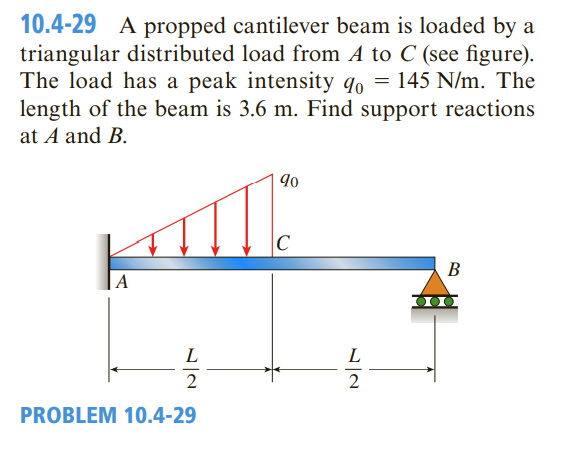
10.4-29 A propped cantilever beam is loaded by a triangular distributed load from A to C (see figure). The load has a peak intensity qo = 145 N/m. The length of the beam is 3.6 m. Find support reactions at A and B. C В |A 2
Q: A cantilever beam AB is subjected to a concentrated load P and a couple MQ acting at the free end…
A: Given data as per question The concentrated load applied =P The couple applied =M0 θB=Area of MEI…
Q: Problem 1 For the beam in the figure below, assume E = 29,000 ksi and I = 600 in“ for the whole…
A: Since we only answer up to 3 subparts, we will answer the first 3. Please resubmit the question by…
Q: A cantilever beam of length L= 1 m supports a load P = 8 kN, shown in figure. The beam is made of…
A:
Q: An overhanging beam ABC has a guidedsupport at A, a rectangular cross section, and supportsan upward…
A:
Q: . A cantilever beam with square cross-section of 6 mm side is subjected to a load of 2 kN normal to…
A: Load, W= 2 kN= 2000 NSide length of the square, a= 6 mmYoung's modulus, E= 210 GPa= 210000…
Q: 5.5-4 A simply supported wood beam AB with a span length L = 4 m carries a uniform load of inten-…
A:
Q: 4. The beam with rectangular cross-section b xh having dimensions b = 25 mm, and h = 50 mm, of…
A:
Q: Draw the shear-force and bending-momentdiagrams for a simple beam AB supporting twoequal…
A: To draw the shear force and bending moment diagrams of the given figure, we must calculate the…
Q: A laminated plastic beam of square cross section is built up by gluingtogether three strips, each 10…
A: Given total weight , W = 3.6 N, span length, L = 360 mm τallow=0.3 MPa σallow=8MPa We need to…
Q: A cantilever beam of length L= 5 m supports a load P = 8 kN, shown in figure. The beam is made of…
A: The given values are - P= 8kN , b= 110 mm ,h= 190 mm , L= 5m
Q: A cantilever beam of length L= 5 m supports a load P = 8 kN, shown in figure. The beam is made of…
A:
Q: maximum shear stress and normal stress in the beams.
A:
Q: the beam are as follows: IPN 280 section, L = 3.5 m, P = 18 kN, and a = 26.57°. (Note: See Table E-2…
A:
Q: A simply supported composite beam 3 m long carries a uniformly distributed load of intensity q=3…
A:
Q: The cantilever beam in the figure has a fixed support at A and is under the actions of a uniformly…
A:
Q: 3 kN/m +x A B C 4.0 m 4.0 m A propped 8m prismatic beam ABCD shown in the figure is loaded with a…
A:
Q: 5.5-21 A cantilever beam, a UPN 300 section, is subjected to its own weight and a point load at B.…
A:
Q: A laminated plastic beam of square cross section is built up by gluing together three strips, each…
A:
Q: 10.4-13 Beam ABC is fixed at support A and rests (at point B) upon the midpoint of beam DE (see the…
A: The deflection diagram of the beam without considering beam DE is given as, The maximum deflection…
Q: 5.5-12 A small dam of height h = 2.0 m is constructed of vertical wood beams AB of thickness t = 120…
A:
Q: A horizontal beam AB with cross-sectional dimensions (b = 0.85 in.) x (h = 8.0 in.) is supported by…
A:
Q: A beam with a guided support and 10 t span supports a distributed load of intensity a630 Ib/t over…
A: Given:
Q: 711. A cantilever beam BD rests on a simple beam AC as shown in Fig. P-711. Both beams are of the…
A:
Q: The homogeneous beam shown in the figure is suspended by a cable at point B and is pin supported at…
A:
Q: A horizontal beam AB with cross-sectional dimensions (b = 0.75 in.) X (h = 8.0 in.) is supported by…
A:
Q: Calculate the shape factor j for the wide-flange beam shown in the figure if h = 12.2 in., b =…
A: Given Data The height of the beam is: h=12.2 in The width of the beam is: b=8.08 in The flange…
Q: 10.4-13 Beam ABC is fixed at support A and rests (at point B) upon the midpoint of beam DE (see the…
A: The general expression for deflection at any point x in a cantilever beam in that the load P is…
Q: 5 planks (4@ 40 x 40 mm and 1@40 x 380 mm), joined together forming |-section (shown in figure).…
A:
Q: A three-span continuous beam ABCD with three equal spans supports a uniform load of intensity q (see…
A: Given data as per question Uniform distributed load = q Calculations Drawing FBD of the beam three…
Q: The flexural rigidity (EI) of a cantilever beam is assumed to be constant over the length of the…
A:
Q: A laminated plastic beam of square cross section is built up by gluing together three strips, each…
A: GIVEN: TO FIND:
Q: A steel beam ABC is simply supported at Aand B and has an overhang BC of length L =150 mm(see…
A: Given: To determine: a) Disregarding the weight of the beam, the required width b of the…
Q: The Cantilever beam ABC in figure below (a) consist of two segment AB and 21, for segment BC.…
A: When any beam is subjected to load, the beam tends to deviate. When a beam deflects, the neutral…
Q: A simple beam AB supports five equally spaced loads P (see figure). Find the reactions at the…
A:
Q: Q 1. A simple supported beam of span 9m carries two points loads 210 KN & 125 KN at 2m & 6m from…
A: Given:- the span of simple supported beam=9m Uniform distribution load throughout the beam…
Q: 4. For the beam shown in the figure determine the following: (El = constant) a. value of El0 at A b.…
A: The movement of a beam or node from its original position is referred to as deflection in structural…
Q: H.W 4 A simple beam on a 10 ft span supports a uniform load of intensity 800 lb/ft (see figure). The…
A: Answer: (a) The maximum bending stress in the wooden member is 365.5064 psi. (b) The maximum bending…
Q: 200 kN 100 kN/m 100 kN.m 1m 1 1m 2m 3m Figure 1: An overhanging beam For the same beam and loading…
A:
Q: H.W Draw shear force and bending moment diagrams for a cantilever beam as shown in Figure? I KN/m-…
A:
Q: Horizontal beam ACB with cross section dimensions (width = b) (height = h) as shown in the figure…
A: (a) Consider the free body diagram of the given figure as shown below.
Q: 10.4-2 A fixed-end beam AB carries point load P acting at point C. The beam has a rectangular cross…
A:
Q: Beam ABCD is simply supported at B and C and has overhangs at each end (see Fig, a). The span length…
A: Here two different types of loading are being applied on the overhanging beam ABCD. Shear forces and…
Q: A propped cantilever beam AB of a length L carries a concentrated load P acting at the position…
A: There are three unknowns (RA, RB, and Rc) and only two equations. This is a statistically…
Q: The hollow circle cross section of the simply supported beam shown in the figure. Find the maximum…
A: For solution refer below images.
Q: Draw the shear-force and bending-moment diagrams for beam AB with asliding support at A and an…
A: Consider the reaction at B is RB. The horizontal reaction force at A is HA. The moment at end A is…
Q: A tapered cantilever beam AB of length L hassquare cross sections and supports a concentratedload P…
A: hB = 3hA To-Find:- a) Magnitude σmax of the maximumbending stress b) Ratio of the maximumstress to…
Q: Beam AB in the figure is clamped at end A and has a plain bearing at end B (See figure). The beam…
A: given data; ⇒load intensity (q)=15KN/m⇒length (l)=8m⇒lets take reaction force at B=RB⇒lets take…
Q: please answer the question
A: MAB=-400×108=-500 kN-mMBA=500 kN-mMBC=30×10212=30×10012=-250 kN-mMCB=250 kN-m
Q: 8.4-10 An overhanging beam ABC has a guided support at A, a rectangular cross section, and sup-…
A: We have to determine the above question
Trending now
This is a popular solution!
Step by step
Solved in 3 steps with 4 images
- A propped cantilever beam of length L = 54 in. with a sliding support supports a uniform load of intensity q (see figure). The beam is made of steel {<7y = 36 ksi) and has a rectangular cross section of width/) = 4.5 in. and height h = 6.0 in. What load intensity q will produce a fully plastic condition in the beam?A simple beam AB is subjected to a load in the form of a couple M0 acting at end B (see figure). Determine the angles of rotation A and B at the supports and the deflection at the midpoint.Solve the preceding problem for a wide-flange beam with h = 404 mm, b = 140 mm, bf= 11.2 mm, and rf. = 6.99 mm.
- A cantilever beam is subjected to load P at mid-span and counterclockwise moment Mat B (see figure). Find an expression for moment M in terms of the load P so that the reaction moment MAat A is equal to zero. Find an expression for moment M in terms of the load P so that the deflection isêp = 0; also, what is rotation Find an expression for moment M in terms of the load P so that the rotation also, what is deflectionA uniformly loaded, steel wide-flange beam with simple supports (see figure) has a downward deflection of 10 mm at the midpoint and angles of rotation equal to 0.01 radians at the ends. Calculate the height h of the beam if the maximum bending stress is 90 MPa and the modulus of elasticity is 200 GPa, (Use the formulas of Example 9-L)A simply supported beam (E = 1600 ksi) is loaded by a triangular distributed load from A to C(see figure). The load has a peak intensity q0= 10 lb/ ft, and the deflection is known to be 0.01 in, at point C. The length of the beam is 12 ft, and the ratio of the height to the width of the cross section is (h:b) 2:1, Find the height h; and width h of the cross section of the beam.
- Two flat beams AB and CD, lying in horizontal planes, cross at right angles and jointly support a vertical load P at their midpoints (see figure). Before the load P is applied, the beams just touch each other. Both beams are made of the same material and have the same widths. Also, the ends of both beams are simply supported. The lengths of beams AB and CD are LABand LCD, respectively. What should be the ratio tABltCDof the thicknesses of the beams if all four reactions arc to be the same?A wide-flange beam (W 12 x 35) supports a uniform load on a simple span of length L = 14 ft (see figure). Calculate the maximum deflection max at the midpoint and the angles of rotation Sat the supports if q = 1.8 kips/ft and E = 30 × 106 psi. (Use the formulas of Example 9-1.)-14 A simply supported composite beam with a 3.6 m span supports a triangularly distributed load of peak intensity q0at mid-span (see figure part a). The beam is constructed of two wood joists, each 50 mm x 280 mm, fastened to two steel plates, one of dimensions 6 mm × 80 mm and the lower plate of dimensions 6 mm x 120mm (see figure part b). The modulus of elasticity for the wood is 11 GPa and for the steel is 210 GPa. If the allowable stresses are 7 MPa for the wood and 120 MPa for the steel, find the allowable peak load intensity q0maxwhen the beam is bent about the z axis. Neglect the weight of the beam.
- A steel beam ABC is simply supported at A and held by a high-strength steel wire at B (see figure). A load P = 240 lb acts at the free end C. The wire has axial rigidity EA = 1500 x 103 lb, and the beam has flexural rigidity EI = 36 X 106 lb-in". What is the deflectionA steel beam ABC is simply supported at A and fiand has an overhang BC of length L = 150 mm (see figure). The beam supports a uniform load of intensity q = 4,0 kN/m over its entire span AB and l.5g over BC. The cross section of the beam is rectangular with width h and height 2b. The allowable bending stress in the steel iso"a|]ûW = 60 MPa, and its weight density is y = 77.0 kN/m . Disregarding the weight of the beam, calculate the required width b of the rectangular cross section. Taking into account the weight of the beam, calculate the required width b.A simple beam of length L = 5 m carries a uniform load of intensity q = 5,8 kN/m and a concentrated load 22.5 kN (see figure). (a) Assuming tra]]ow = 110 MPa, calculate the required section modulus S. Then select the most economical wide-flange beam (W shape) from Table F-l(b) in Appendix F, and recalculate S, taking into account the weight of the beam. Select a new beam if necessary. (b) Repeat part (a), but now assume that the design requires that the W shape must be used in weak axis bending (i.e., it must bend about the 2-2 (or y) axis of the cross section).