10A. Calculate the power consumed of the load, load impedance and power factor of the load. c) What is the difference between primary and secondary standards of measurements? Question 4 a) The secondary winding burden of CT having a har primary and 240 secondary turns, has an ammete: resistance and reactance of I chm and 05 uhms tespeetively. The resistance of secondary winding is 0.5 chms and the reactance is 0.25 The core requires munf of 100 AT for magnictisation and 50 AT for core losses. Determine the primary winding current. the actual trunsformation ratio when the ammeter reads 5A, Ihe numher of turns which could be recuced in the secondary winding sa that the ration error comes zero. b) The following readings were chtained from three voltmeters Ined for single phase power micasurements V2-200V across the non-inductive resistor, V3-220V across the nductive load, VI=350V acrmss the two volimerers in weirs. Cakculate the power factor of the non- inductive load. c) Define PCLS and stute their main advantages over hard wired relaye. Question 5 a) The series clunmeter in Fig. Q5. I below is made up of a 3 V hattery and a resistance R, which makes (RI + Ra)= 15 kn. (a) Determine the instrument indication when Rx -0. (b) Determine how the resistance scale should be marked at 0.5 FSD. 0.25 FSD, and 0 75 FSD Resistance ta be measured Sandard resistance R. Meier resistance Battery- Mrier Fig. QS. 1 b) An analog indicating instrument with a scale range of 0 to 50 V shows a voltage on 2 8! V. The true value of the reading is 2.90 volts.
10A. Calculate the power consumed of the load, load impedance and power factor of the load. c) What is the difference between primary and secondary standards of measurements? Question 4 a) The secondary winding burden of CT having a har primary and 240 secondary turns, has an ammete: resistance and reactance of I chm and 05 uhms tespeetively. The resistance of secondary winding is 0.5 chms and the reactance is 0.25 The core requires munf of 100 AT for magnictisation and 50 AT for core losses. Determine the primary winding current. the actual trunsformation ratio when the ammeter reads 5A, Ihe numher of turns which could be recuced in the secondary winding sa that the ration error comes zero. b) The following readings were chtained from three voltmeters Ined for single phase power micasurements V2-200V across the non-inductive resistor, V3-220V across the nductive load, VI=350V acrmss the two volimerers in weirs. Cakculate the power factor of the non- inductive load. c) Define PCLS and stute their main advantages over hard wired relaye. Question 5 a) The series clunmeter in Fig. Q5. I below is made up of a 3 V hattery and a resistance R, which makes (RI + Ra)= 15 kn. (a) Determine the instrument indication when Rx -0. (b) Determine how the resistance scale should be marked at 0.5 FSD. 0.25 FSD, and 0 75 FSD Resistance ta be measured Sandard resistance R. Meier resistance Battery- Mrier Fig. QS. 1 b) An analog indicating instrument with a scale range of 0 to 50 V shows a voltage on 2 8! V. The true value of the reading is 2.90 volts.

Power System Analysis and Design (MindTap Course List)
6th Edition
ISBN:9781305632134
Author:J. Duncan Glover, Thomas Overbye, Mulukutla S. Sarma
Publisher:J. Duncan Glover, Thomas Overbye, Mulukutla S. Sarma
Chapter2: Fundamentals
Section: Chapter Questions
Problem 2.48P

Related questions
Question
Answer question 4
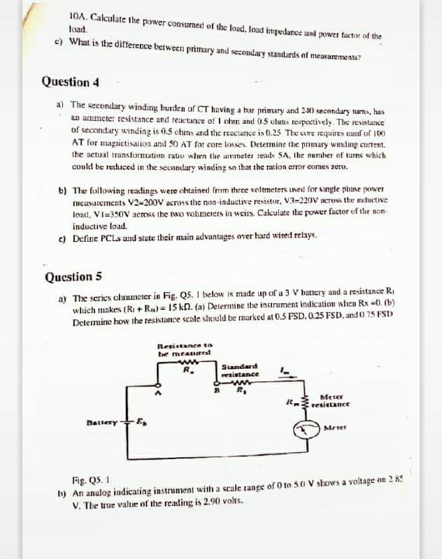
Transcribed Image Text:10A. Calculate the power consumed of the load, loud impedance and power factor of the
load.
c) What is the difference between primary and secondary standards of measurements"
Question 4
a) The secondary winding burden of CT having a har primary and 240 secondary tuns, has
an ammete: resistance and reactance of I chm and 05 uhuns respeetively. The reSistance
of secondary winding is 0.5 chms and the reactance is 0.25 The core requires manf of 100
AT for magrietisation and 50 AT for core losses. Determine the primary winding current.
the actual trunsformation ratio when the ummeter reads SA, Ibe number of turns which
could be recuced in the secondary winding so that the ration error comes zero.
b) The fallowing readings were ohtained from three voltmeters used for single phase power
mcusurements V2=200V across the non-inductive resistor, V3-220V aeross the mnductive
load, VI=350V across the two volimeers in weirs. Cakulate the power factor of the non-
inductive load.
c) Define PCLS and state their main advantages over hard wired relays.
Question 5
a) The series clunmeter in Fig. Q5. 1 below is made up of a 3 V hattery and a resistance R,
which makes (RI + Rm) = 15 kn. (a) Determine the instrument indication when Rx =0. (b)
Determine how the resistance scale shuld be marked at 0.5 FSD. 0.25 FSD, and 0 75 FSD
Resistance ta
be measured
R.
Standard
resistance
Meter
resietance
Battery+E,
Mrier
Fig. QS. 1
h) An analog indicating instrument with a scale range of 0 to 50 V shows a voltage on 2 85
V. The true value of the reading is 2.90 volts.
Expert Solution
This question has been solved!
Explore an expertly crafted, step-by-step solution for a thorough understanding of key concepts.

Step by step
Solved in 5 steps

Recommended textbooks for you
Power System Analysis and Design (MindTap Course …
Electrical Engineering
ISBN:
9781305632134
Author:
J. Duncan Glover, Thomas Overbye, Mulukutla S. Sarma
Publisher:
Cengage Learning
Power System Analysis and Design (MindTap Course …
Electrical Engineering
ISBN:
9781305632134
Author:
J. Duncan Glover, Thomas Overbye, Mulukutla S. Sarma
Publisher:
Cengage Learning