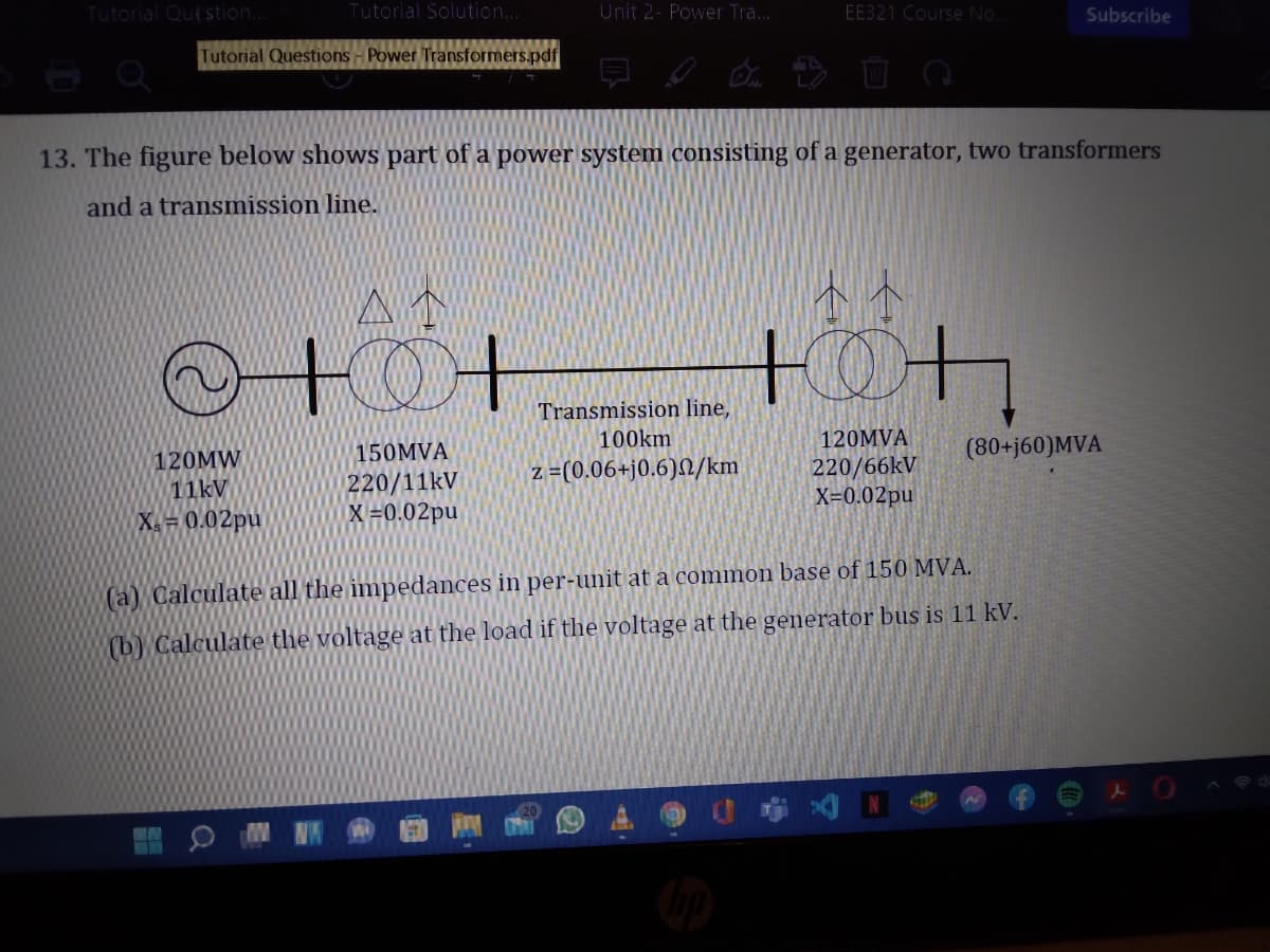
13. The figure below shows part of a power system consisting of a generator, two transformers and a transmission line. +0+ Transmission line, 150MVA 100km 120MVA 120MW 11kV (80+j60)MVA z =(0.06+j0.6)N/km 220/11kV X=0.02pu 220/66KV X=0.02pu X= 0.02pu (a) Calculate all the impedances in per-unit at a common base of 150 MVA. (b) Calculate the voltage at the load if the voltage at the generator bus is 11 kV.
Q: How
A: Solution How does a Direct On Line Motor Starter work?
Q: talk about Earth's radiative budget, what happens to electromagnetic radiation as it enters Earth's ...
A: Electromagnetics Radiation electromagnetic radiation is the branch of physics which flow of energy i...
Q: The maximum flux density in the core of a 250/3000-volts, 50Hz single-phase transformer is 1.2T. If ...
A:
Q: Obtain the Zin for the circuit shown. 50 2 j30 2 ele j100 Q 60 Q Lin 40 2 j20 N Zin = Blank 1+ jBlan...
A:
Q: 3. Simplify the following expressions and implement them using two level NAND Gate crcuits (a) AB + ...
A:
Q: 9 Teo cos ABa conneced in seres as a sOH, 300V souroe. The resstance of the col As40and inductance o...
A:
Q: T13. Fill the table given below from the understanding of Doping of Semiconductor materials. N type ...
A: N type and P type semiconductors are the types of Extrinsic semiconductor. Doping is the process of ...
Q: What is the RMS value of 169sin 377t?
A: Given sinusoid is 169sin 377t.
Q: 8. Two capacitors, a 20 µF and a 30 µl а. 12 иF b. 50 µF
A:
Q: A unity negative feedback control system has the loop transfer function L(s) = G{s)G(s): K %3D s(s +...
A: In this question ,Negative feedback system is given...We have to find out percentage overshoot and s...
Q: R R1 R2 N1 Lout I in Fig. 1: Current to voltage converter with T network 2.1. Derive an expression f...
A:
Q: Thevenin Circuit only.
A: For Thevenin resistance- Independent voltage source is short circuited and independent current sourc...
Q: A device used to protect a circuit against over currents is a what? a. Polyswitch b. Capacitor c. D...
A: A device used to protect a circuit against our current is called fuse.
Q: . Consider a device connected to an ac power supply. The current leads the voltage by 90°, with the ...
A: (a) Since the current leads the voltage by 90° the given device is capacitor. (b) The angular freque...
Q: Using diode equation, find the p-n junction diode current for a forward bias of 0.22V at room temper...
A:
Q: It contains a resistor, an inductor, and a capacitor in
A:
Q: 10. Referring to problem 9, find the Norton equivalent resistance Rn between terminals a and b.
A: This question belongs to circuit theory . It is based on the concept of Norton's equivalent resistan...
Q: n 800-m 2-wire d.c. distributor AB fed from both ends is uniformly loaded at the rate of 1.25 A/mete...
A:
Q: 3. What are the different ways of getting mechanical energy to run a generator?
A: Generator- A machine or a device which converts mechanical energy into electrical energy.
Q: Given: Step- down transformer 2300 / 230 V, r1 -0.093Ω, r2-0.00093Ω , x1 =0.2800 , x2= 0.00280Q. The...
A:
Q: For the following circuit, find i(t) for t > 0. t = 0 12 2 ww 24 2 6 A i(t) 2H ww all
A:
Q: 4 Determine the total resistance, current and the voltage across each resistor. R2 R V 1.0 kO kΩ V R...
A:
Q: A current source in a linear circuit has is = 10 cos(460πt - 32o) A. Calculate is at t = 5 ms.
A: SOLUTION:- is = 10cos (460πt +32°) ACompare to Acos (wt+ϕ)ϕ = 32°in radian , ϕ = 32 ×π180 =0.5585 r...
Q: What is the probability of error with a PSK system with a bit rate of 20kpbs, BW of 50 kHz, Noise po...
A: The solution is given below
Q: 1) Find the reduce transfer function of the following. H
A:
Q: The capacitance between two plates increases with __________. Select one: a. Shorter pla...
A:
Q: What is the noise density for a receiver with an input bandwidth of 20 MHz and an equivalent noise t...
A: We need to find out noise power density .
Q: 11.a. The total loss in a fiber link is 7.1 dB, the design margin is 1 dB, and the optical budget in...
A: "Since you have asked multiple question, we will solve the first question for you. If you want any s...
Q: c) Determine the decimal value of the Q3.2 2's complement number 110010. d) Determine the maximum an...
A: Since you have asked multiple question, we will solve the first question for you. If you want any sp...
Q: difference between the characteristics and operational modes of a differential amplifier from an ope...
A: DIFFERENTIAL AMPLIFIER :- It is the basic building block of the analog circuit. It is the input...
Q: Determine the input impedance of the circuit shown below in rectangular form at @ = 2 rad/s. Show yo...
A:
Q: A 20-hp, 3-phase, 400-V, 60-Hz 4-pole induction motor delivers full-load at5% slip. The mechanical r...
A: Solve for the shaft power. Psh=20 hp=20×746 W=14920 W Solve for the speed of the shaft as, N=120fP1-...
Q: (a) An electrodynamic wattmeter is used to measure the electrical power in a circuit. The diagram in...
A:
Q: Determine the current through 480, use silicon for the diodes and forward resistance of each diode i...
A:
Q: Solve for the Vrms (magnitude only) across the resistance if R2 = 1093 ohms and Xc = 2318 ohms. ... ...
A:
Q: Quèstion 6 NPN BJT is considered as two diodes their anodes are connected together. True False
A: A transistor is a 3 layer 2 junction device and is available in two formats. One of them is PNP and ...
Q: 2- Figure 1 illustrates the first three stages of a typical AM receiver, calculate a- The total gain...
A: We are authorized to answer only three subparts at a time so i am answering only 3 subparts please r...
Q: What should be done with light sources that are connected at each end of a cable while it's being r...
A: For proper safety, we should always take care of certain measures and steps needed to be taken while...
Q: 6. Three capacitors, a 12 µF, a 20 µF and a 30 µF, are connected in series. What is the total capaci...
A: Given: Three capacitors are connected in series C1=12 μFC2=20 μFC3=30 μF
Q: Solve for the value of the capacitance (in nF unit) if R2 = 1035 ohms and Xc = 2132 ohms. Round y...
A:
Q: ·Calculate the output voltage and zener diode current in the regulator circuit 15 V (B = 100) V,o- (...
A: In this question, We need to calculate the output voltage and zener diode current in the regulator ...
Q: 1) A LTI system has an impulse response, h(t) and input signal, x(t). Evaluate the response for the ...
A:
Q: 3. Complete the following table. fci fc BW fo a. 800 Hz 12 kHz b. 5 kHz 10 kHz c. 200 kHz 198 kHz
A:
Q: What is the total potential drop through the complete, closed loop shown below? 2 mH 4 nF 1 k 2 1. a...
A: According to KVL sum of the voltages in closed loop is zero. Voltages can be voltage rise or voltag...
Q: The zener diode in Fig. 17.32 has values ofl man) - 3 mA and Iz(max) =100 mA. What is the minimum al...
A: In this question, We need to determine the minimum allowable value of resistance RL Using the KCL...
Q: The sequences below are digital sequences except.
A:
Q: Please help me answer this problem. Choose the correct answer from the given choices. Put whether yo...
A: In this question we will find open circuit or thevenin voltage in first question and thevenin equiva...
Q: 20.a. A –0.5 dBm signal is transmitted through a fiber link. The transceiver at the receiving end ha...
A: Since you have asked multiple question, we will solve the first question for you. If you want any sp...
Q: Problem 26: Use mesh analysis to find the current through the resistor R5. R5 3 N 4 N R2 10 N R1 R6 ...
A:
Q: 12 v 202 lor Tou lov
A:
Step by step
Solved in 3 steps with 3 images
- Consider the single-line diagram of the power system shown in Figure 3.38. Equipment ratings are Generator 1: 1000MVA,18kV,X=0.2perunit Generator 2: 1000MVA,18kV,X=0.2p.u. Synchronous motor 3: 1500MVA,20kV,X=0.2p.u. Three-phase -Y transformers T1,T2,T3,T4,: 1000MVA,500kV,Y/20kV,X=0.1p.u. Three-phase YY transformer T5: 1500MVA,500kV,Y/20kVY,X=0.1p.u. Neglecting resistance, transformer phase shift, and magnetizing reactance, draw the equivalent reactance diagram. Use a base of 100 MA and 500 kV for the 50-ohm line. Determine the per-unit reactances.Consider Figure 3.25 of the text for a transformer with off-nominal turns ratio. (i) The per-unit equivalent circuit shown in part (c) contains an ideal transformer which cannot be accommodated by some computer programs. (a) True (b) False (ii) In the - circuit representation for real c in part (d), the admittance parameters Y11 and Y12 would be unequal. (a) True (b) False (iii) For complex c, can the admittance parameters be synthesized with a passive RLC circuit? (a) Yes (b) NoAn infinite bus, which is a constant voltage source, is connected to the primary of the three-winding transformer of Problem 3.53. A 7.5-MVA,13.2-kV synchronous motor with a sub transient reactance of 0.2 per unit is connected to the transformer secondary. A5-MW,2.3-kV three-phase resistive load is connected to the tertiary Choosing a base of 66 kV and 15 MVA in the primary, draw the impedance diagram of the system showing per-unit impedances. Neglect transformer exciting current, phase shifts, and all resistances except the resistive load.
- Consider two interconnected voltage sources connected by a line of impedance Z=jX, as shown in Figure 2.27. (a) Obtain expressions for P12 and Q12. (b) Determine the maximum power transfer and the condition for it toA single-phase 100-kVA,2400/240-volt,60-Hz distribution transformer is used as a step-down transformer. The load, which is connected to the 240-volt secondary winding, absorbs 60 kVA at 0.8 power factor lagging and is at 230 volts. Assuming an ideal transformer, calculate the following: (a) primary voltage, (b) load impedance, (c) load impedance referred to the primary, and (d) the real and reactive power supplied to the primary winding.Consider a single-phase electric system shown in Figure 3.33. Transformers are rated as follows: XY15MVA,13.8/138kV, leakage reactance 10 YZ15MVA,138/69kV, leakage reactance 8 With the base in circuit Y chosen as 15MVA,138kV determine the per-unit impedance of the 500 resistive load in circuit Z, referred to circuits Z, Y, and X. Neglecting magnetizing currents, transformer resistances, and line impedances, draw the impedance diagram in per unit.
- Consider Figure 3.4. For an ideal phase-shifting transformer, the imda nce is unchanged when it is referred from one side to the other. (a) True (b) FalseConsider the single-Line diagram of a power system shown in Figure 3.42 with equipment ratings given: Generator G1: 50MVA,13.2kV,x=0.15p.u. Generator G2: 20MVA,13.8kV,x=0.15p.u. Three-phase -Y transformer T1: 80MVA,13.2/165YkV,X=0.1p.u. Three-phase Y- transformer T2: 40MVA,165Y/13.8kV,X=0.1p.u. Load: 40MVA,0.8PFlagging,operatingat150kV Choose a base of 100 MVA for the system and 132-kV base in the transmission-line circuit. Let the load be modeled as a parallel combination of resistance and inductance. Neglect transformer phase shifts. Draw a per-phase equivalent circuit of the system showing all impedances in per unit.Consider the oneline diagram shown in Figure 3.40. The three-phase transformer bank is made up of three identical single-phase transformers, each specified by X1=0.24 (on the low-voltage side), negligible resistance and magnetizing current, and turns ratio =N2/N1=10. The transformer bank is delivering 100 MW at 0.8 p.f. lagging to a substation bus whose voltage is 230 kV. (a) Determine the primary current magnitude, primary voltage (line-to-line) magnitude, and the three-phase complex power supplied by the generator. Choose the line-to-neutral voltage at the bus, Va as the reference Account for the phase shift, and assume positive-sequence operation. (b) Find the phase shift between the primary and secondary voltages.
- A single-phase two-winding transformer rated 90MVA,80/120kV is to be connected as an autotransformer rated 80/200kV. Assume that the transformer is ideal. (a) Draw a schematic diagram of the ideal transformer connected as an autotransformer. showing the voltages, currents, and dot notation for polarity. (b) Determine the permissible kVA rating of the autotransformer if the winding currents and voltages are not to exceed the rated values as a two-winding transformer. How much of the kA rating is transferred by magnetic induction?Figure 3.39 shows a oneline diagram of a system in which the three-phase generator is rated 300 MVA, 20 kV with a subtransient reactance of 0.2 per unit and with its neutral grounded through a 0.4- reactor. The transmission line is 64km long with a cries reactance of 0.5-/km. The three-phase transformer T1 is rated 350MVA.230/20kV with a leakage reactance of 0.1 per unit. Transformer T2 is composed of three single-phase transformers, each rated 100 MVA, 127/13.2kV with a leakage reactance of 0.1 per unit. Two 13.2kV motors M1 and M2 with a subtransient reactance of 0.2 per unit for each motor represent the load. M1 has a rated input of 200 MVA with its neutral grounded through a 0.4- current-limiting reactor, M2 has a rated input of 100 MVA with its neutral not connected to ground. Neglect phase shifts associated with the transformers. Choose the generator rating as base in the generator circuit and draw the positive-sequence reactance diagram showing all reactances in per unit.With the same transformer banks as in Problem 3.47, Figure 3.41 shows the oneline diagram of a generator, a step-up transformer bank, a transmission line, a stepown transformer bank, and an impedan load. The generator terminal voltage is 15 kV (line-to-line). (a) Draw the per-phase equivalent circuit, aounting for phase shifts for positive-sequence operation. (b) By choosing the line-to-neutral generator terminal voltage as the reference, determine the magnitudes of the generator current, transmiss ion-line current, load current, and line-to-line load voltage. Also, find the three-phase complex power delivered to the load.