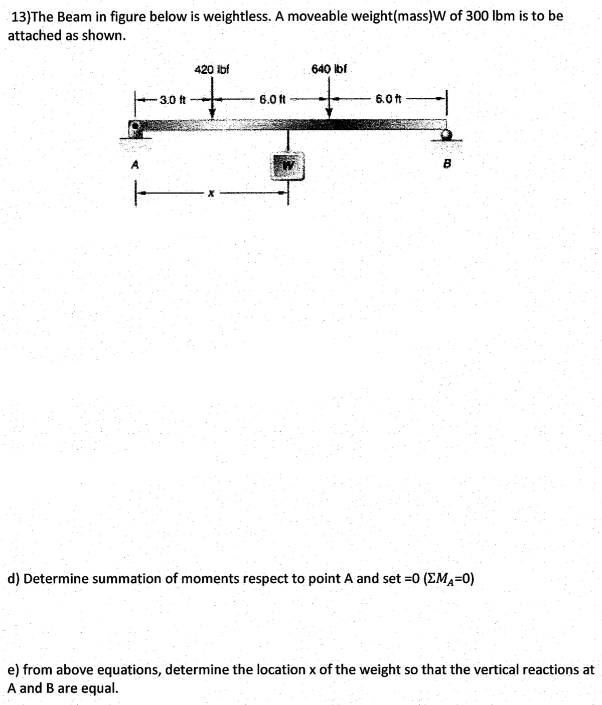
13)The Beam in figure below is weightless. A moveable weight(mass)W of 300 Ibm is to be attached as shown.
Q: 2. From the roof truss shown in Figure 5.18, compute the following members using method of sections:…
A:
Q: 1. For the beam shown below, calculate the support reactions. 200 lb Fixed support 38 Ib/ft 6 ft 6…
A:
Q: Anchor of the beam given in the figure is built-in support, B point is movable support and G joint.…
A: Let the reactions at fixed support 'A' be: RAH , RAV , MA. Let the reactions at pin joint 'G' be:…
Q: 6. Way 28 mm diameter steel and 20 mm A composite beam made of aluminum rods in diameter. Elasticity…
A:
Q: For figure below, the tension in the cable is
A: given:
Q: Given the Statically Determinate Propped Beam as shown below with internal hinged at Point B. The…
A: (a) Draw the free-body diagram of the beam.
Q: A boom with an angle of theta, supports a 1000lbs load, as shown in the figure. Assume that the…
A: Given data: The magnitude of load, W = 1000 lb. Force exerted by the boom (FB) is 3 times the force…
Q: Calculate reactions at pin support A and B, take beam AB weight 30 Kg. B 60° А 1 Add file
A:
Q: hown in Fig. 1. Q2. The compound beam shown in Fig.2. is pin supported at B and supported by rockers…
A:
Q: Uniformly distributed load of 5 kN acts on a simply supported beam of length 10 m. What are the…
A:
Q: Q.2) Draw the shear force and bending moment diagrams for the distributed load and two reaction…
A: draw the shear force and bending moment diagram.
Q: A 125ON sphere in figure is supported by the pull P and a 83ON weight passing over a frictionless…
A:
Q: 9. The frame shown in Figure 1-67 is supported in pivots at A and B. Each member weighs 50 lb per…
A:
Q: Given the beam problem shown in Fig 1.1
A: a) Free body diagram of known and unknown forces:
Q: SKN/m 4m 12 IKN Mae 4 3m 3 m REFER TO FIGURE 03, DETERMINE THE MAGNITUDE AND LOCATION OF THE…
A:
Q: A simply supported beam, 3 in wide by 3 in deep, carries a uniformly distributed load of 80 lb/ft…
A:
Q: 5. Given Figure 1,, neglect the weight of the beam.. Determine the vertical reaction in Kn AT A
A: Moment: It is the product of the force with its perpendicular distance from the reference point.…
Q: For the simply supported beam and the loading shown in the figure find the hinge forces ( B ) and…
A: Solution:
Q: A simply supported beam is loaded as shown in the Figure. The corresponding SFD and BMD would be: 20…
A:
Q: Q.2) Draw the shear force and bending moment diagrams for the distributed load and two reaction…
A: First calculate the reactions then draw the Shear force diagram and bending moment diagram
Q: For the prismatic beam attached to the load shown in the figure, get the reactions and show them in…
A: .
Q: Anchor point of the beam given in the figure is fixed support and B point is movable support. Find…
A:
Q: The vertical reaction in the hinged support shown in the figure is Blank 1 N.
A:
Q: A rectangular steel beam, (75) mm wide by (150) mm deep, is loaded as shown in figure. Determine:
A:
Q: For the figure shown below, compute the bending moment in section 1. Neglect the weights of the…
A:
Q: Find magnitude and nature (tensile or compressive) of force in the members BD, BE, CE, HF, HG & IG…
A: Draw the free-body diagram of the truss.
Q: Load on member AB for truss as shown in the figure is,
A: Given: A structure,
Q: 3. For the beam shown below, calculate the support reactions. 80 lb 38 Ib/ft A B 6 ft 8 ft 6 ft
A:
Q: A beam is loaded as shown in the figure. What is the location of the concentrated load from point B?
A: Consider the diagram of the beam as shown below. Here W1 is the triangular load and the W2 is the…
Q: Q-4 Compute the value of Ely at midspan for the beam loaded shown in fig (12.5 ) 500 N 450 N/m A B…
A: Let the reaction at A and B be RA + RB. RA + RB = 500 + 450×2 = 1400Taking the moment about D, we…
Q: For the figure shown below, compute the bending moment in section 1. Neglect the weights of the…
A:
Q: Solve using integration and please show graph: A horizontal beam 10 ft long has a variable load,…
A: The expression of total shear force experienced by the beam is given by:- V=∫0Lωxdx where,ωx=load…
Q: For the frame shown in the figure , the bending moment at Bequals
A:
Q: A simply supported beam is loaded as shown in the Figure. The corresponding SFD and BMD would be: 20…
A:
Q: For the frame shown in figure below, the rotation at (A) equals:
A:
Q: Draw a Free-Body Diagram of the bars AD and BC shown in the figure. Assume all hinges to be smooth…
A:
Q: determine reaction A (in kN, roundiff to 2 decimal places) for the loaded beam in the figure.
A: Given Beam under action of loads as shown in figure To find reaction at hinge A
Q: A 2 kN/m -5m- Figure 4 3 m 10 kN Į -2 m- B
A: Given
Q: (4) The Jib crane shown in figure carries load of W. If the maximum load in the tie is 25 kN,…
A: Given data: The free body diagram of the setup is,
Q: 250 kN 40 kN/m 20 kN/m I (m) 1 2.5 5 Figure.1: Simply supported beam Your tasks are as follows: 1-…
A:
Q: Q3: For the structure shown in Figure, Compute the forces in all pines. 50 Ib 80 Ib 6 ft (20 Degree)
A:
Q: 1. Refer on the given beam below. Take note that points B and C are internal hinges.
A: TO FIND :
Q: For the given Frame, draw SFD and BMD. 10 kips 4 ft B C 2 kip/ft 10 ft A 8 ft
A: Equilibrium is a state of a body at which there is no disturbance in a system neither inside nor…
Q: 1. For the beam shown below, calculate the support reactions. 200 lb Fixed support 38 Ib/ft 60° 6 ft…
A:
Q: 3. For a beam shown below in Fig. 3. Answer questions a-e, given in the box below the space. 50KN 20…
A: Given DataP=50kNM=50kN.mθ=80° ***As question simply demands for the reactions***
Q: 3. For the beam shown below, calculate the support reactions. 80 lb 38 Ib/ft A 6 ft 8 ft 6 ft 00
A:
Q: 10. Figure 6 shows two cables AB and BC supporting a 1500 N load. A C 2.50 m 2.25 m 3.00 m 1500 N…
A: Find the length of Ab and BC also find force in AB and BC
Q: 1.5 in. 90 lb/ft 0.75 in. 800 lb
A:
Trending now
This is a popular solution!
Step by step
Solved in 2 steps with 2 images
- A fixed-end beam AB of a length L is subjected to a uniform load of intensity q acting over the middle region of the beam (sec figure). Obtain a formula for the fixed-end moments MAand MBin terms of the load q, the length L, and the length h of the loaded part of the beam. Plot a graph of the fixed-end moment MAversus the length b of the loaded part of the beam. For convenience, plot the graph in the following nondimensional form: MAqL2/l2versusbL with the ratio b/L varying between its extreme values of 0 and 1. (c) For the special case in which ù = h = L/3, draw the shear-force and bending-moment diagrams for the beam, labeling all critical ordinates.A foot bridge on a hiking trail is constructed using two timber logs each having a diameter d = 0.5 m (see figure a). The bridge is simply supported and has a length L = 4 m. The top of each log is trimmed to form the walking surface (see Fig, b)LA simplified model of the bridge is shown in Fig. g. Each log must carry its own weight w = 1.2 kN/m and the weight (P = 850 N) of a person at mid-span, (see Fig. b). Determine the maximum tensile and compressive stresses in the beam (Fig, b) due to bending. If load h is unchanged, find the maximum permissible value of load ... if the allowable normal stress in tension and compression is 2.5 M Pa.A heavy object of weight W is dropped onto the midpoint of a simple beam AB from a height h (see figure). Obtain a formula for the maximum bending stress ^ma* due to tne filing weight in terms of h, st, and 5st, where it is the maximum bending stress and Sstis the deflection at the midpoint when the weight W acts on the beam as a statically applied load. Plot a graph of the ratio o"max/ö"it (that is, the ratio of the dynamic stress to the static stress) versus the ratio iifS^r(Let h/S^ vary from 0 to 10.)
- Find support reactions at A and D and then calculate the axial force N, shear force V, and bending moment M at mid-span of AB. Let L = 14 ft, q0 = 12 lb/ft, P = 50 lb. and = 300 lb-ft.A large precast concrete panel for a warehouse is raised using two sets of cables at two lift lines, as shown in the figure part a. Cable 1 has a length L1 = 22 Ft, cable 2 has a length L2= 10 ft, and the distance along the panel between lift points Band D is d = 14 ft (see figure part b). The total weight of the panel is W = 85 kips. Assuming the cable lift Forces F at each lift line are about equal, use the simplified model of one half of the panel in figure part b to perform your analysis for the lift position shown. Find the required cross-sectional area AC of the cable if its breaking stress is 91 ksi and a factor of safety of 4 with respect to failure is desired.A steel riser pipe hangs from a drill rig located offshore in deep water (see figure). (a) What is the greatest length (meters) it can have without breaking if the pipe is suspended in the air and the ultimate strength (or breaking strength) is 550 MPa? (b) If the same riser pipe hangs from a drill rig at sea, what is the greatest length? (Obtain the weight densities of steel and sea water from Table M, Appendix I. Neglect the effect of buoyant foam casings on the pipe.)
- Find expressions for shear force V and moment M at v = L/2 of beam AB in structure (a). Express V and M in terms of peak load intensity q0and beam length variable L. Repeat for structure (b) but find Fand M at m id-span of member BC.-4-4 A cantilever beam is supported at B by cable BC. The beam carries a uniform load q = 200 N/M. If the length of the beam is L = 3 m, find the force in the cable and the reactions at A. Ignore the axial flexibility of the cable.Repeat Problem 11.3-9. Use two C 150 × 12.2 steel shapes and assume that E = 205 GPa and L = 6 m.
- A long re Lai nine: wall is braced by wood shores set at an angle of 30° and supported by concrete thrust blocks, as shown in the first part of the figure. The shores are evenly spaced at 3 m apart. For analysis purposes, the wall and shores are idealized as shown in the second part of the figure. Note that the base of the wall and both ends of the shores are assumed to be pinned. The pressure of the soil against the wall is assumed to be triangularly distributed, and the resultant force acting on a 3-meter length of the walls is F = 190 kN. If each shore has a 150 mm X 150 mm square cross section, what is the compressive stressAt a full d raw, an archer applies a pull of 130 N to the bowstring of the bow shown in the figure. Determine the bending moment at the midpoint of the bow.Two flat beams AB and CD, lying in horizontal planes, cross at right angles and jointly support a vertical load P at their midpoints (see figure). Before the load P is applied, the beams just touch each other. Both beams are made of the same material and have the same widths. Also, the ends of both beams are simply supported. The lengths of beams AB and CD are LABand LCD, respectively. What should be the ratio tABltCDof the thicknesses of the beams if all four reactions arc to be the same?