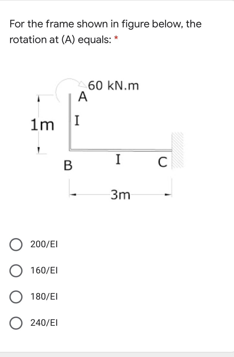
For the frame shown in figure below, the rotation at (A) equals:


Q: A uniformly distributed force of C kN/m and a concentrated load of D kN are applied to a cantilever…
A:
Q: A hanging weight, with a mass of m, = 0.350 kg, is attached by a rope to a block with mass m, =…
A: Given data as per the question mass m1=0.350 kgmass m2=0.830 kgmass of pulleyM=0.350 KGRadius…
Q: Figure 2 A 2.00 m long horizontal uniform beam of mass 20.0 kg is supported by a string as shown in…
A:
Q: The automobile engine block in the figure is suspended by a system of cables. The mass of the block…
A:
Q: 10 kips 3 kips/ft A 3 ft 4 ft 3 ft Draw the moment diagram by parts in your solution sheet. Assume…
A:
Q: The assembly in the given figure is consists of steel and aluminium bars and it is fixed at the wall…
A:
Q: Consider the frame shown in Fig 4. A 100N load is suspended around a fixed drum with radius 2 m…
A:
Q: Assume the plate shown in Figure has negligible weight. There is a ball and socket joint at A and a…
A:
Q: For figure below, the tension in the cable is
A: given:
Q: The figure above illustrates a system comprising a rigid support structure having a cross-sectional…
A:
Q: In the figure, one end of a uniform beam of weight 480 N is hinged to a wall; the other end is…
A:
Q: Q. 60. The figure shows a schematic layout of a hydraulic jack. The load to be raised weighs 20,000…
A:
Q: 6. For the following wire rope diameters of 6 x 19 type wire rope, with steel core, find the…
A: The list of all parameters related to 6×19 type wire rope, with a steel core is given as Now, take…
Q: Two loads 400N and 500N are suspended in a vertical plane by three springs as shown in Figure. Find…
A:
Q: 2. Draw the free body diagram of the figure below.
A: Free body diagram is the diagram which shows all the forces acting on a body.
Q: Determine the force Vectors F = 90 N and F43 in the four bar mechanism shown in figure below. Draw…
A: Given: F = 90 N OQ = 80 cm OA = 50 cm AB = 70 cm QB = 60 cm QE = 34 cm For this mechanism to be…
Q: The reaction at the support B of the beam shown in below figure is 2 EN 3 kN B 45° 2 m 2 m 2 m 3 m 2…
A:
Q: The following figure shows a 4 m bar fixed to the wall through a hinge that rotates freely, but is…
A:
Q: Find the Tensions TCA and TCB for the system as shown in figure. Take P = 140 mm, Q= 120 mm 8 = 35°,…
A: Draw the free-body diagram of joint C. Calculate the angle given in the above diagram.…
Q: A 125ON sphere in figure is supported by the pull P and a 83ON weight passing over a frictionless…
A:
Q: A board of mass mand length l is attached to a wall and a rope that makes an angle of theta, as…
A: Given data: Image with relevant details To determine: Magnitude of tension…
Q: A simple truss is subjected to 20 kN force at point A as shown in Figure 2. The reaction force at…
A:
Q: 1. A beam 3 m long weighing 400 N is suspended in a horizontal position by twe vertical strings,…
A: According to the question, length of beam l=3m a 400N load is applied at C. Let C be the mid point…
Q: The two bearings (B1) and (B2) are used to support a shaft as shown in the figure Using the data…
A:
Q: For the prismatic beam attached to the load shown in the figure, get the reactions and show them in…
A: .
Q: 8. Refer to figure 9. Given the following information: angles 0r= 20°, 02= 30°, 03= 41°, a 200 N…
A:
Q: Anchor point of the beam given in the figure is fixed support and B point is movable support. Find…
A:
Q: For the frame shown in figure below, number of unknown displacements equals * C A 1.0 m I I I В P.
A: Given,
Q: Figure Q3 represents an over-hanging beam, with a pin-support at point A and a rolling support at…
A: As per our guidelines we are supposed to solve only 3 subparts if multiple subparts are asked .…
Q: 4. Give practical applications of wire ropes. What are the advantages of wire ropes? 5. What is the…
A: Hello. Since you have posted multiple questions and not specified which question needs to be solved,…
Q: 5. In relation to question show free body diagram of the below figure
A:
Q: SITUATION 4. Given the figure below, find the: |31 kN 5-25 mm Ф bolts 70 mm 8D mm 80 mm 70 mm T31 KN…
A:
Q: P-1500 kg 45 Py-4000kg k P:
A:
Q: In the figure, one end of a uniform beam of weight 130 N is hinged to a wall; the other end is…
A:
Q: bent bar shown in figure is supported at A with a ball-and-sc a cable and a link, and the support at…
A:
Q: For the frame shown in the figure , the bending moment at Bequals
A:
Q: D L ft 60° 60 30° 30 E L f- L ft In the figure, L = 10, P1 = 750 lb, and P2 = 620 lb. Compute the…
A:
Q: In the figure, one end of a uniform beam of weight 130 N is hinged to a wall; the other end is…
A: To find: The tension in the wire. Given: The weight of the one end of the beam is hinged to the wall…
Q: In the figure below, a weight W is suspended from point D of a beam AD. The beam is held up by rod…
A: Consider the above truss carefully. Consider the beam AD, in this it can be seen that there are 3…
Q: Find the Tensions TCA and TCB for the system as shown in figure. Take R = 200 mm, S= 240 mm 0 = 55°,…
A: Given: The weight is W = 14 kN, The dimension R =200 mm, The dimension S =240 mm, The angle θ=55°.
Q: Given the loading criteria in the figure below, find all reaction forces. |80 kN 30 kN/m 2m 3m 2m
A: A uniformly distributed load (UDL) is a load that is evenly distributed throughout the whole…
Q: A utility hook was formed from a round rod of diameter d= 0.75 in into the geometry shown in the…
A: The data given is, Round rod diameter, d = 0.75 in Force, F = 1500 lbf Length, L = 7 in Inner…
Q: 4/ For the figure below the spring is used to stop a 10 package. If the maximum deflection in the…
A:
Q: A rod is attached to a pivot on the wall at one end and suspended horizontally at the other end by a…
A: Given: Suspended mass (m)=1kgMass of the rod (M)=2kgLength of the rod (L)=4m
Q: Figure Q3 shows a steel bar of diameter 16 mm and length 600 mm subjected to axial forces If E =…
A:
Q: Now, if the end of the bar marked by the red circle in the figure below is the only spot where you…
A: There are three types of loading 1. Point load 2. UDL 3. UVL Point load is the simplest form and it…
Q: The following figure shows three situations in which the same horizontal rod is supported by a hinge…
A: For better understanding, arbitrarily assign some value on the external force acting on the rod Let…
Q: 300 lb A 4 in. Fig. P5.7 C 240 lb 360 lb D E 3 in. 4 in. 5 in. B
A:
Q: A simple truss is subjected to 20 kN force at point A as shown in Figure 2. The reaction force at…
A:


Step by step
Solved in 2 steps with 2 images


- Repeat Problem 11.2-3 assuming that R= 10 kN · m/rad and L = 2 m.Two steel wines support a moveable overhead camera weighing W = 28 lb (see figure part a) used For close-up to viewing of field action at sporting, events. At some instant, wire I is at an angle a = 22° to the horizontal and wire 2 is at angle fi = 40°. Wires I and 2 have diameters of 30and 35 mils, respectively. (Wire diameters are often expressed in mils; one mil equals 0.001 in.) (a) Determine the tensile stresses s and s2 in the two wires. (b) If the stresses in wires 1 and 2 must be the same, what is the required diameter of wire 1 ? (c) To stabilize the camera for windy outdoor conditions, a third wire is added (see figure part b). Assume the three wires meet at a common point coordinates (0, 0. 0) above the camera at the instant shown in figure part b. Wire I is attached to a support at coordinates (75 ft, 48 ft, 70 Ft). Wire 2 is supported at (-70 ft. 55 ft, 80 Ft). Wire 3 is supported at (-10 ft. -85 Ft, 75 ft). Assume that all three wires have a diameter of 30 mils. Find the tensile stresses in all three wiresRepeat Problem 11.3-9. Use two C 150 × 12.2 steel shapes and assume that E = 205 GPa and L = 6 m.
- A cable and pulley system at D is used to bring a 230-lcg pole (ACB) to a vertical position, as shown in the Figure part a. The cable has tensile force T and is attached at C. The length L of the pole is 6.0m, the outer diameter is d = 140 mm. and the wall thickness is t = 12 mm. The pole pivots about a pin at A in figure part b. The allowable shear stress in the pin is 60 MPa and the allowable bearing stress is 90 MPa. Find the minimum diameter of the pin at A in order to support the weight of the pole in the position shown in the figure part a.The figure shows an idealized structure consisting of two rigid bars with pinned connections and linearly elastic rotational springs. Rotational stiffness is denoted ßR. Determine the critical load Pcrfor the structure.A small lab scale has a rigid L-shaped frame ABC consisting of a horizontal aim AB (length b = 30 cm) and a vertical arm BC (length c = 20 cm) pivoted at point B. The pivot is attached to the outer frame BCD that stands on a laboratory bench. The position of the pointer at C is controlled by two parallel springs, each having a spring constant k = 3650 N/m. that are attached to a threaded rod. The pitch of the threads is p = 1.5 mm. If the weight is 65 N. how many revolutions of the nut are required to bring the pointer back to the mark?
- Repeat Problem 2.4-8, but assume that the bar is made of aluminum alloy and that BC is prismatic. Assume that P = 20 kim. L = 3 ft.t = 314 in., b1 2m.b 2.Sin.andElO.400ksi.A large precast concrete panel for a warehouse is raised using two sets of cables at two lift lines, as shown in the figure part a. Cable 1 has a length L1 = 22 Ft, cable 2 has a length L2= 10 ft, and the distance along the panel between lift points Band D is d = 14 ft (see figure part b). The total weight of the panel is W = 85 kips. Assuming the cable lift Forces F at each lift line are about equal, use the simplified model of one half of the panel in figure part b to perform your analysis for the lift position shown. Find the required cross-sectional area AC of the cable if its breaking stress is 91 ksi and a factor of safety of 4 with respect to failure is desired.Three round, copper alloy bars having the same length L but different shapes are shown, in the figure. The first bar has a diameter d over its entire length, the second has a diameter d over one-fifth of its length, and the third has a diameter d over one-fifteenth of its length. Elsewhere, the second and third bars have a diameter Id. All three bars are subjected to the same axial load P. Use the following numerical data: P = 1400 kN, L = 5m,d= 80 mm, E= 110 GPa. and v = 0.33. (a) Find the change in length of each bar. (b) Find the change in volume of each bar.
- A small lab scale has a rigid L-shaped frame ABC consisting of a horizontal arm AB (length b = 10 in.) and a vertical arm BC (length c = 7 in.) pivoted al point B. The pivot is attached to the outer frame BCD that stands on a laboratory bench. The position of the pointer al C is controlled by a spring, Jt = 5 lb/in., that is attached to a threaded rod. The pitch of the threads is p = 1/16 in. Under application of load W, 12 revolutions of the nut are required to bring the pointer back to the mark. Calculate the weight W.A suspender on a suspension bridge consist of a cable that passes over the main cable (see figure) and supports the bridge deck, which is Far below. The suspender is held in position by a metal tie that is prevented from sliding downward by clamps around the suspender cable. Let P represent the load in each part of the suspender cable, and let represent the angle of the suspender cable just above the tie. represent the allowable tensile stress in the metal tie. (a) Obtain a formula for the minimum required cross-sectional area of the lie. (b) Calculate the minimum area if P = 130 kN, = 75°, and allow=80 .A lifeboat hangs from two ship's davits. as shown in the figure. A pin of diameter d = 0.80 in. passes through each davit and supports two pulleys. are on each side of the davit. Cables attached to the lifeboat pass over the pulleys and wind around winches that raise and lower the lifeboat. The lower parts of the cables are vertical and the upper parts make an angle a =15° with the horizontal. The allowable tensile force in each cable is 1800 lb, and the allowable shear stress in the pins is 4000 psi. If the lifeboat weighs 1500 lb, what is the maximum weight that can be carried in the lifeboat?