For the frame shown in the figure , the bending moment at Bequals

Mechanics of Materials (MindTap Course List)
9th Edition
ISBN:9781337093347
Author:Barry J. Goodno, James M. Gere
Publisher:Barry J. Goodno, James M. Gere
Chapter1: Tension, Compression, And Shear
Section: Chapter Questions
Problem 1.3.22P: Find support reactions at A and D and then calculate the axial force N. shear force 1 and bending...

Related questions

Question
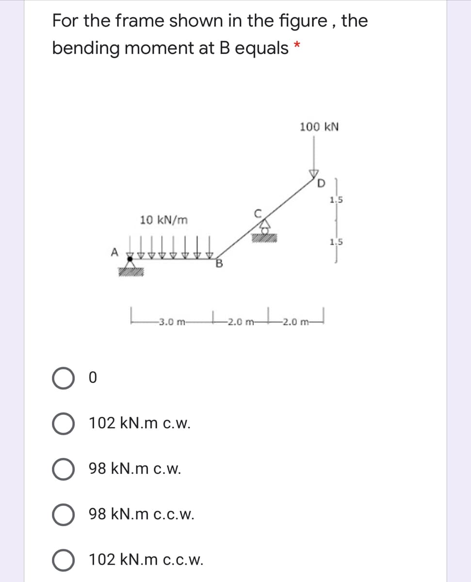
Transcribed Image Text:For the frame shown in the figure , the
bending moment at B equals *
100 kN
1,5
10 kN/m
1,5
A
B.
+20m20m
-3.0 m-
-2.0 m-
O 102 kN.m c.w.
98 kN.m c.w.
98 kN.m c.c.W.
O 102 kN.m c.c.w.
Expert Solution
This question has been solved!
Explore an expertly crafted, step-by-step solution for a thorough understanding of key concepts.

Step by step
Solved in 2 steps with 2 images

Knowledge Booster


Learn more about
Need a deep-dive on the concept behind this application? Look no further. Learn more about this topic, mechanical-engineering and related others by exploring similar questions and additional content below.Recommended textbooks for you
Mechanics of Materials (MindTap Course List)
Mechanical Engineering
ISBN:
9781337093347
Author:
Barry J. Goodno, James M. Gere
Publisher:
Cengage Learning
Mechanics of Materials (MindTap Course List)
Mechanical Engineering
ISBN:
9781337093347
Author:
Barry J. Goodno, James M. Gere
Publisher:
Cengage Learning