2.0 m L2 1.0 m A beam is supported by a pin connection at B and a roller support at D. An upwards force Fi-1.5 kN acts at the left end of the beam (point A). A ightwards force P-17.5 kN acts at the right end of the beam (point E). A undormly distributed load wy1.8 kN/m pushes down on the beam between points Cand E. The separation betwoen A and 8 is Li 1 m, and the separation between C and Dis La 2 m
2.0 m L2 1.0 m A beam is supported by a pin connection at B and a roller support at D. An upwards force Fi-1.5 kN acts at the left end of the beam (point A). A ightwards force P-17.5 kN acts at the right end of the beam (point E). A undormly distributed load wy1.8 kN/m pushes down on the beam between points Cand E. The separation betwoen A and 8 is Li 1 m, and the separation between C and Dis La 2 m

Mechanics of Materials (MindTap Course List)
9th Edition
ISBN:9781337093347
Author:Barry J. Goodno, James M. Gere
Publisher:Barry J. Goodno, James M. Gere
Chapter1: Tension, Compression, And Shear
Section: Chapter Questions
Problem 1.10.17P: Continuous cable A DB runs over a small friction less pulley al D to support beam OABC, which is...

Related questions

Question
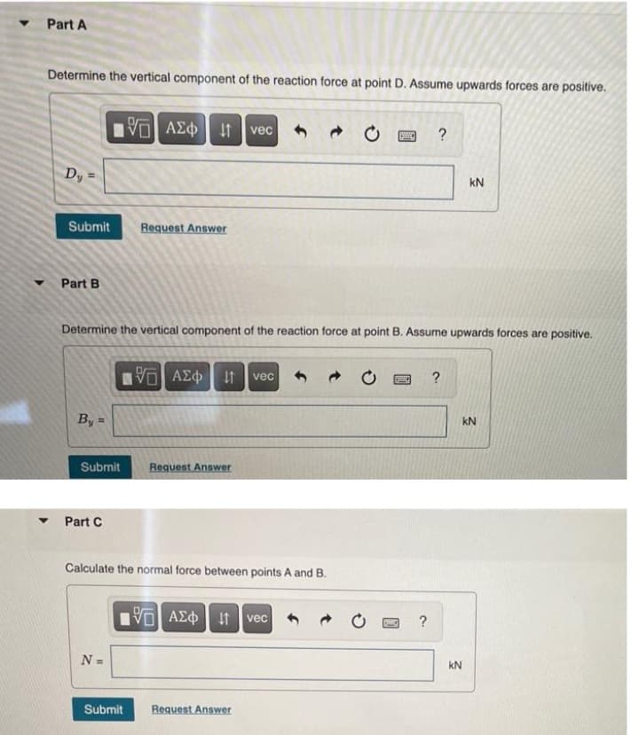
Transcribed Image Text:Part A
Determine the vertical component of the reaction force at point D. Assume upwards forces are positive.
VO AEO t
vec
?
Dy
kN
Submit
Request Answer
Part B
Determine the vertical component of the reaction force at point B. Assume upwards forces are positive.
It
vec
?
By =
kN
Submit
Request Answer
Part C
Calculate the normal force between points A and B.
VOAEO t vec
N =
kN
Submit
Request Answer
Transcribed Image Text:W1
F1
F2
A
C
2.0 m
L2
1.0 m
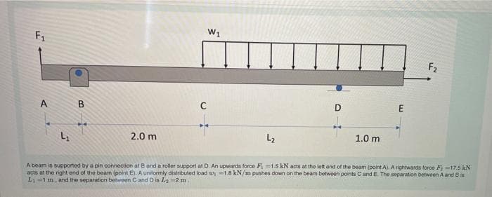
A beam is supported by a pin connection at B and a rollor support at D. An upwards force Fi =1.5 kN acts at the loft end of the beam (point A). A rightwards force F17.5 kN
acts at the right end of the bearn (point E). A unitormly distributed load w1.8kN/m pushes down on the beam between points C andE The separation betwoen A and Bis
L =1 m, and the separation between Cand D is La-2 m
Expert Solution
This question has been solved!
Explore an expertly crafted, step-by-step solution for a thorough understanding of key concepts.

This is a popular solution!

Trending now
This is a popular solution!

Step by step
Solved in 2 steps with 2 images

Knowledge Booster


Learn more about
Need a deep-dive on the concept behind this application? Look no further. Learn more about this topic, mechanical-engineering and related others by exploring similar questions and additional content below.Recommended textbooks for you
Mechanics of Materials (MindTap Course List)
Mechanical Engineering
ISBN:
9781337093347
Author:
Barry J. Goodno, James M. Gere
Publisher:
Cengage Learning
Mechanics of Materials (MindTap Course List)
Mechanical Engineering
ISBN:
9781337093347
Author:
Barry J. Goodno, James M. Gere
Publisher:
Cengage Learning