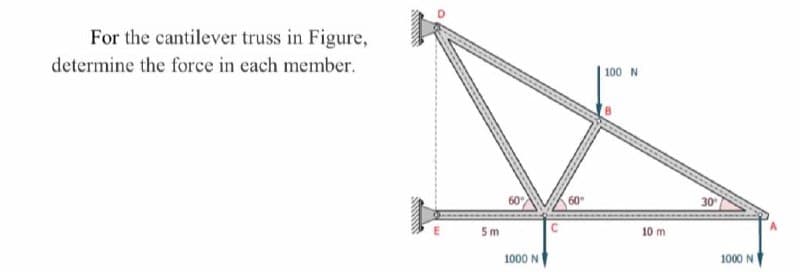
For the cantilever truss in Figure, determine the force in each member. | 100 N 60 30 5m 10 m 1000 N 1000 N


Q: BLOCK C CABLE FRICTION p = 0.35 for all surfaces In the beam system shown in the figure, Block A and…
A:
Q: In the train bridge in the figure, select the F1 and F2 forces from 107 to 207 kN with a non- zero…
A: A pin support will exert both horizontal and vertical components of reaction as the reaction forces.…
Q: A distributed force and a concentrated force act on the 20m long bar shown below. 2 kN 400 N/m A B *…
A:
Q: This is a question from the textbook, Example 3.1 from page 132. We are interested in the…
A:
Q: In the figure below, a pulley can pull a 1-ton load from rest to 3 m/s upwards at 2 seconds. AB and…
A: Given: The load, W = 1 ton The speed, v = 3 m/s The time, t = 2 s The compressive stress, σ = 140…
Q: The steel beams shown in the figure are combined with a total of 12 rivets with a diameter of 12 mm.…
A: The given shear strength of the material is
Q: FH, EH, and EG of the cage system for the loading condition given in Figure. Calculate the rod…
A: A pin support will exert both horizontal and vertical components of reaction. The support B is pin…
Q: Two identical trusses support a load of 100 N as shown in the figure. The length of each truss is…
A: Given:
Q: An aluminum rod is rigidly attached between a steel rod and a bronze rod as shown in the figure.…
A: Draw a free body diagram for the beam. Here, R is the horizontal reaction at the fixed support.…
Q: Rigid bar BC is supported by aluminum rod (1) and bronze rod (2), as shown in the figure. Aluminum…
A:
Q: Find the stress in members DF, FI, and HI if the cross- sectional area of each member is 800 mm².…
A:
Q: Q2 A flat plate with a central hole is subjected to an axial tensile force F of 9.8 KN, as shown in…
A:
Q: The BC rod, which is assumed to be rigid and massless in Figure, stands horizontally with the help…
A: Draw the deflection diagram. From the deflection diagram, the relation between deflections is,
Q: The cantilever truss in the figure is hinged at D and E. Find the force in member BD. 1000 1b 60 60…
A:
Q: The truss is attached to the wall with a horizontal force and a vertical force applied as specified…
A:
Q: Calculate the magnitude of the force (in kN) on bar AB. Take P = 30.0 kN, do not put units in the…
A: .
Q: For the rigid frames shown in Figure, determine the displacements and rotations of the nodes, the…
A: Given: The elastic modulus, E = 210 GPa The cross-sectional area, A = 1 x 10⁻² m^2 The moment of…
Q: A F F W2 d A Section A-A The following figure shows the free-body diagram of a connecting-link…
A: FROM DATA BOOK, Sut=64kpsi Sy=54kpsi a=2.7 b=-0.265 kb=1 kc=0.85 endurance limit, Se=0.5Sut…
Q: Question cm is subject to 4 forces of 1 kN each applied at the edges of the plate with a 45-degree…
A: First of all we have to resolve these forces along x and y axes. The inclined forces then becomes…
Q: Determine the maximum shear force in kN in the figure below. 30 kN 140 kN • m A D В C +2 m- 3 m 2 m→
A:
Q: three steel wires, each 28 mm2 in area, are used to lift a mass M. Their unstretched lengths are…
A: Given data: Cross-section area of the steel wire = 28 mm2 Length of each steel wire = 19.99 m, 19.98…
Q: Q.2) Consider a truss ABC loaded at A with a force 20 N as shown in figure. 20 N A The load in…
A:
Q: Q.1) For the plate shown in figure, determine the forces in three ropes if the plate weighs 1.6 kN.…
A: Determine the position vector along AB, AC and AD.
Q: Four axial forces are applied to the 25mm thick structural steel bar with 40mm diameter pins as…
A: The given force member is as shown below,
Q: 15 kN/m 10 kN 20 kN.m B AV D 12 kN 2m 2m 1.5m 2m
A: Shear Force is the net vertical force on either side of the section The effect of the shear force is…
Q: Q.1) A plane truss is loaded as shown in the figure. What is magnitude of force in the member CD and…
A: use method of section cut a section xx Take moment about point C 500*20 +100*10 = FBD*203 FBD =…
Q: rmine the forces in all bars of the truss shown in the given figure. Indicate tension or…
A:
Q: 1. A homogeneous 800 kg bar AB is supported at either end by a cable. Calculate the smallest area of…
A: To find: The smallest area of each cable. Given: The mass of bar AB is m=800 kg. The stress is not…
Q: 1. A tripod supports the load W as shown in the figure. a. Determine the maximum load "W* that can…
A:
Q: P 50 mm 100 mm 200 mm 0.09 mm B unloaded E A Rigid D 150 mm C 300 mm
A:
Q: Compound axial member ABC has a uniform diameter of d = 2.9 in. Segment (1) is an aluminum [E₁ =…
A: INTRODUCTION: A composite bar is constructed of two bars of different materials that are firmly…
Q: A mechanism carries a constant load P applied to the seat as E shown. Calculate the forces, in…
A: Forces in mechanisms can be calculated by balancing them in particular directions. The sum of all…
Q: 2. A horizontal bar of negligible mass, hinged at A in the figure and assumed rigid, is supported by…
A: RS, RB are tensions in steel and bronze Rax and Ray are the rections at pin joint A ∆S ,∆B are…
Q: Determine the maximum shear force in kN in the figure below. 10 kN/m 25 kN • m A E B |C D 1 m 1m 3 m…
A: Answer: The maximum shear force is +/- 20 kN.
Q: The cantilever truss in the figure is hinged at D and E. Find the force in member BD. 1000 1b 60°…
A: As per given question We have to determine all forces members including BD
Q: Q.4] Find the forces in the members of the bridge truss shown below. 5KW 5KN A k B k 12 m 8m с 10 KN…
A:
Q: Q.2) For the truss shown in figure below, determine the forces in lo00 2/E
A: Note:As per our guidelines we are supposed to answer only one question. Kindly repost other…
Q: 13)The Beam in figure below is weightless. A moveable weight(mass)W of 300 lbm is to be attached as…
A: As per our guidelines, we are supposed to answer only first three subparts in case of multiple…
Q: Consider the truss as shown in the figure and parameter table. The maximum allowable tensile force…
A:
Q: Q.4) A truss consists of horizontal members (AC, CD, DB and EF) and vertical members (CE and DF)…
A: In this truss the total load Pl due to uniformly distributed load will at the center of member EF.…
Q: Q2/ A force P = 1 KN applied to a right bar suspended by three wires, as shown below. all wires are…
A:
Q: Determine the maximum shear force in kN in the figure below. 2 kN/m B C A 4 m 2 m 5 kN
A:
Q: A tripod supports the load W as shown in the figure. 2.4 m 1.8 D. 1.8 0.90 1.8 O Determine the…
A:
Q: The simplest truss consists of two rods and is loaded by the force F. Given: F = 5,1 kN. Angle α =…
A:
Q: For the cables shown in the figure, find the forces in each cable if cable C pass over a pulley and…
A: The weight of the holding mass is as follows: W=mgW=10×9.81W=98.1 N The tension in the cable D will…
Q: A slip collar with weight W =150 pounds fallsfrom a heighth = 2inch. Towards a flange located at the…
A:
Q: giew. given in the figure below, is (A) 27 kN (Tensile) (B) 15 kN (Compressive) C) 20 kN…
A:
Q: L1 PB 2 E2 L2 D2 Dimensions: L2 L1 D2 D1 17 mm 18 cm 23 cm 15 mm Problem Statement: The rod shown is…
A: Consider the following diagram showing the forces (loads) acting on the system of two rods of…
Q: The mechanical assembly shown in the figureconsists of an aluminum tube, a rigid end plate, andtwo…
A: Given DataAs = 0.85in2 for each cable, AA = 4.5 in2L = 20 inEs = 29,000 ksiEA = 10,600 ksi, and p =…
Q: For the given figure below, the beam is 57.4 m long. It has a rectangular cross-section area with…
A: Consider the diagram as shown below for the given beam. Here Fs is the spring force.

Step by step
Solved in 5 steps with 4 images

- A steel rod is acted upon by the loading shown below. 50 mm2 is the area of the circular rod. The coupling sizes at B, C, and D are neglected. Use E st = 200 GPa. c) Force in segment CD, PCD=__________ kN, (insert type of force here) d) Total deformation in the assembly, σ = _____________ mmQ5: For the frame and loading shown in Fig.5, compute the horizontal and vertical component of all forces acting on its members. Sin. 10in ¥ l ]lfl;”l = e ; 6in. Fig.5At the nodes in the truss system given in the figure occurring displacement and the stress and reaction that occurs Find the forces.E=200GpaA=10000 mm2
- A load of W = 34 kN is lifted through a boom 'BCD' as shown in the figure. The boom makes an angle of 60 degrees with the vertical. Neglect the weight of the boom for this problem, L1 = L2 = 2.6 m. The pulley at 'D' is frictionless. d.) What is the vertical component at 'B' in kN? e.) Calculate the total reaction at 'B' in kN. *Round off in 4 decimal places. Thank you.9-8kN stress/force on the AB rope holding the base station shown below There are. In order for the net force at point A of this base station to be downward What is the stress/force that should be on the AC rope? A) 5556 N C) 7356 N B) 8200 N D) 3648 N E) 1228 NFind the residual forces acting in a truss with members AC=1000N (T), EG=520N (T), and FH=1200N (C) as indicated in Figure 2. Determine the loads P1, P2, and P3 as well. Use four decimal places.
- 2. FH, EH, and EG of the cage system for the loading condition given in Figure. Calculate the rod forces using the section method. Rod State whether the forces are tensile or compressive. P1(kN)=15 P2(kN)=45 L(m)=3The cross-sectional area of each member of the truss is 1.6in2. Calculate the average normal stresses in members CE, DE, and DF. Indicate whether the stress is in tension or compression. Draw free-body diagramDetermine the internal resultants FG, VG, and MG on the cross section at G of the horizontal frame member in Fig. P1.4-17. The uniformly distributed load on member AC has a magnitude w0=220 lb/ft. (See the inset for a definition of the resultants.)
- using the method of sections , analyse the truss shown in figure 8 below reguarding forces in menbers ED , DF AND FC .6–10. The maximum allowable tensile force in the members of the truss is (Ft)max=1500 lb, and the maximum allowable compressive force is (Fc)max=800 lb. Determine the maximum magnitude P of the two loads that can be applied to the truss. Take a=8 ft.From the system shown in the figure, obtain the forces and the average axial stress on each bar AB, AC and BC. Use the transversal area shown below.