2.1 Determine the reaction forces at the points of support of the beam shown in the figure Q2 above by applying the principle of equilibrium of moments. (Start your solution by drawing a free body diagram of the beam).
2.1 Determine the reaction forces at the points of support of the beam shown in the figure Q2 above by applying the principle of equilibrium of moments. (Start your solution by drawing a free body diagram of the beam).

Mechanics of Materials (MindTap Course List)
9th Edition
ISBN:9781337093347
Author:Barry J. Goodno, James M. Gere
Publisher:Barry J. Goodno, James M. Gere
Chapter2: Axially Loaded Members
Section: Chapter Questions
Problem 2.2.3P: The L-shaped arm ABCD shown in the figure lies in a vertical plane and pivots about a horizontal pin...

Related questions

Question
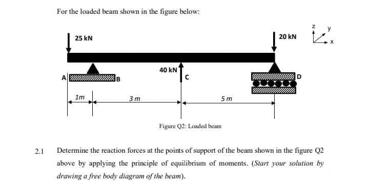
Transcribed Image Text:For the loaded beam shown in the figure below:
y
25 kN
20 kN
40 kN
1m
3 m
5 m
Figure Q2: Loaded beam
2.1
Determine the reaction forces at the points of support of the beam shown in the figure Q2
above by applying the principle of equilibrium of moments. (Start your solution by
drawing a free body diagram of the beam).
Expert Solution
This question has been solved!
Explore an expertly crafted, step-by-step solution for a thorough understanding of key concepts.

This is a popular solution!

Trending now
This is a popular solution!

Step by step
Solved in 3 steps with 3 images

Knowledge Booster


Learn more about
Need a deep-dive on the concept behind this application? Look no further. Learn more about this topic, mechanical-engineering and related others by exploring similar questions and additional content below.Recommended textbooks for you
Mechanics of Materials (MindTap Course List)
Mechanical Engineering
ISBN:
9781337093347
Author:
Barry J. Goodno, James M. Gere
Publisher:
Cengage Learning
Mechanics of Materials (MindTap Course List)
Mechanical Engineering
ISBN:
9781337093347
Author:
Barry J. Goodno, James M. Gere
Publisher:
Cengage Learning