240 V 240 V 25 ΚΩ 75 ΚΩ 30 ΚΩ w • 120 ΚΩ 25 ΚΩ Figure 1 30 ΚΩ ww Vo 75 ΚΩ >7.5 × 10⁴i 120 ΚΩ Vo Figure 2
240 V 240 V 25 ΚΩ 75 ΚΩ 30 ΚΩ w • 120 ΚΩ 25 ΚΩ Figure 1 30 ΚΩ ww Vo 75 ΚΩ >7.5 × 10⁴i 120 ΚΩ Vo Figure 2

Chapter1: General Information For Electrical Installations
Section: Chapter Questions
Problem 14R

Related questions
Question
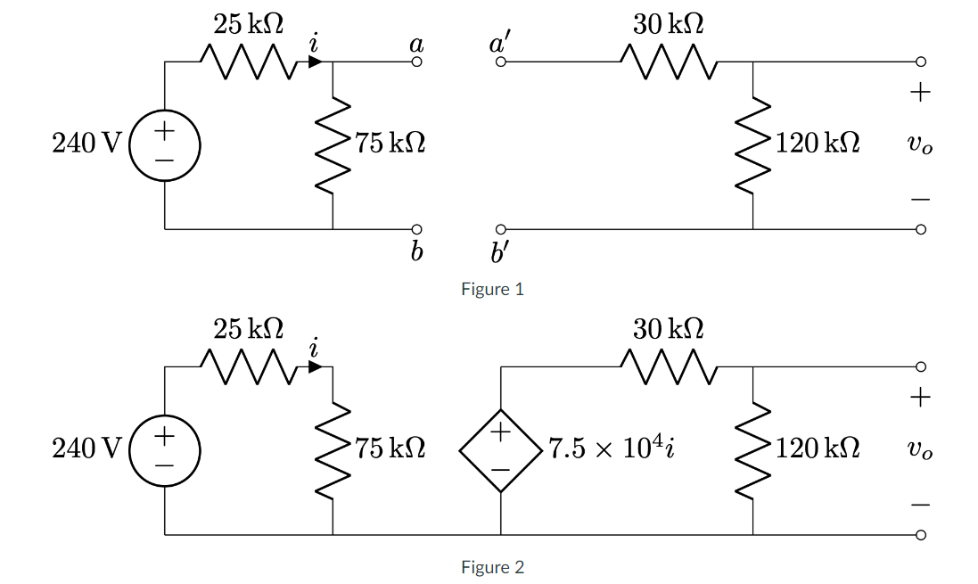
This question centers around two ways to model a load attached to a source. In both of the figures below, the source is the circuit comprising the 240V voltage source and the 25K and 75K resistors.
Figure 1
Figure 2
- In Figure 1, suppose we connect (short) a to a′ and b to b′. Calculate v0.
- As an alternative, calculate v0 if the load is connected to the source as in Figure 2.
- Comment on the differences between your answers to parts A and B.
Transcribed Image Text:240 V
240 V
25 ΚΩ
75 ΚΩ
30 ΚΩ
w
• 120 ΚΩ
25 ΚΩ
Figure 1
30 ΚΩ
ww
Vo
75 ΚΩ
>7.5 × 10⁴i
120 ΚΩ
Vo
Figure 2
Expert Solution
This question has been solved!
Explore an expertly crafted, step-by-step solution for a thorough understanding of key concepts.

This is a popular solution!

Trending now
This is a popular solution!

Step by step
Solved in 2 steps with 2 images

Recommended textbooks for you
EBK ELECTRICAL WIRING RESIDENTIAL
Electrical Engineering
ISBN:
9781337516549
Author:
Simmons
Publisher:
CENGAGE LEARNING - CONSIGNMENT
EBK ELECTRICAL WIRING RESIDENTIAL
Electrical Engineering
ISBN:
9781337516549
Author:
Simmons
Publisher:
CENGAGE LEARNING - CONSIGNMENT