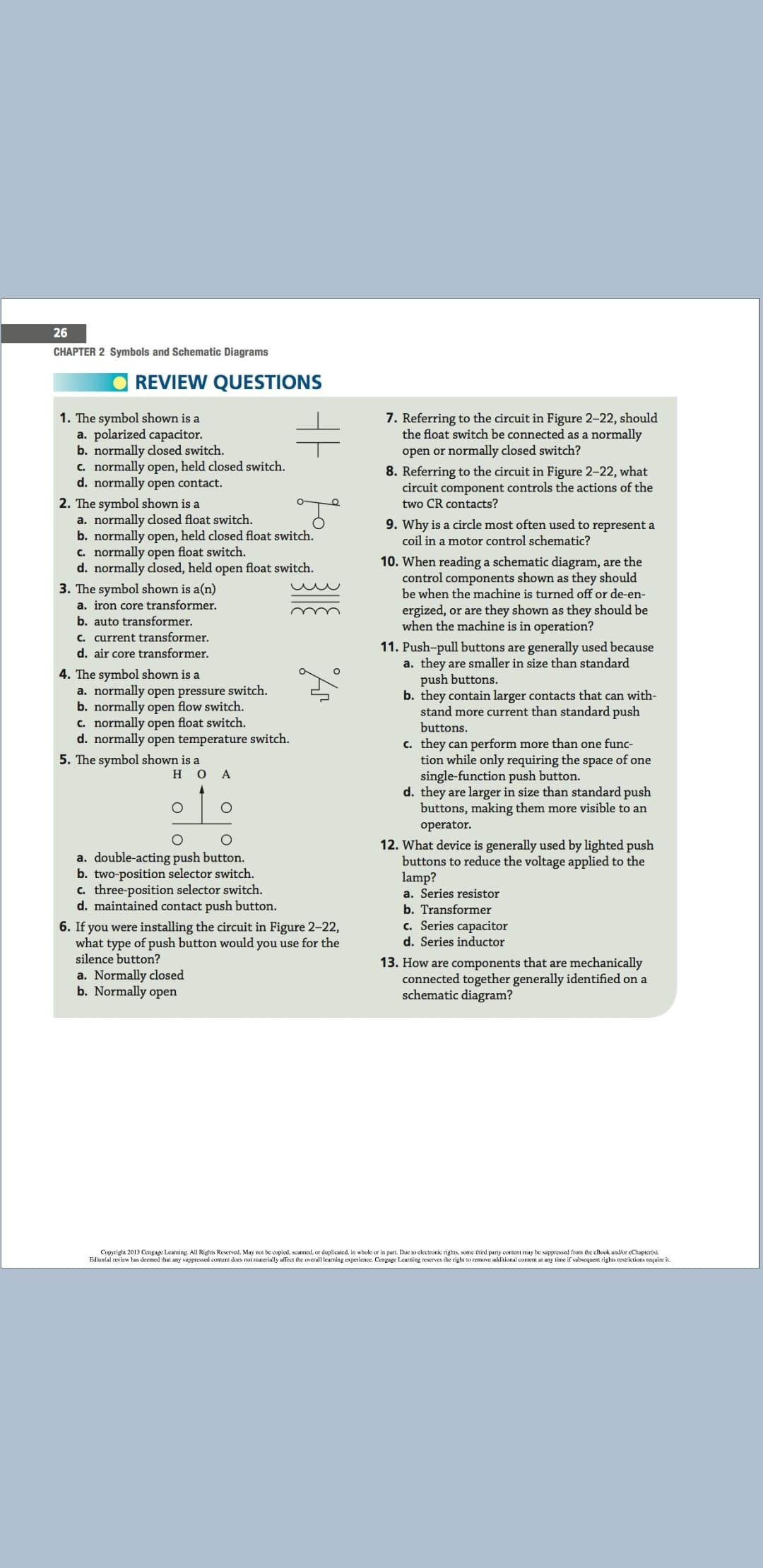
26 CHAPTER 2 Symbols and Schematic Diagrams REVIEW QUESTIONS 7. Referring to the circuit in Figure 2-22, should the float switch be connected as a normally open or normally closed switch? 8. Referring to the circuit in Figure 2-22, what circuit component controls the actions of the two CR contacts? 1. The symbol shown is a a. polarized capacitor. b. normally closed switch. c. normally open, held closed switch. d. normally open contact. 2. The symbol shown is a a. normally closed float switch. b. normally open, held closed float switch. C. normally open float switch. d. normally closed, held open float switch. 9. Why is a circle most often used to represent a coil in a motor control schematic? 10. When reading a schematic diagram, are the control components shown as they should be when the machine is turned off or de-en- 3. The symbol shown is a(n) a. iron core transformer. ergized, or are they shown as they should be when the machine is in operation? b. auto transformer. c. current transformer. 11. Push-pull buttons are generally used because d. air core transformer. a. they are smaller in size than standard push buttons. b. they contain larger contacts that can with- stand more current than standard push buttons. 4. The symbol shown is a a. normally open pressure switch. b. normally open flow switch. C. normally open float switch. d. normally open temperature switch. c. they can perform more than one func- tion while only requiring the space of one single-function push button. d. they are larger in size than standard push buttons, making them more visible to an 5. The symbol shown is a но A operator. 12. What device is generally used by lighted push buttons to reduce the voltage applied to the lamp? a. double-acting push button. b. two-position selector switch. c. three-position selector switch. d. maintained contact push button. a. Series resistor b. Transformer c. Series capacitor d. Series inductor 6. If you were installing the circuit in Figure 2-22, what type of push button would you use for the silence button? 13. How are components that are mechanically connected together generally identified on a schematic diagram? a. Normally closed b. Normally open Copyright 2013 Cengage Learning. ALI Rights Reserved. May x be copied, scanned, or duplicaled, in whole or in part. Due to electronic rights, some third parnty content may be suppressed from the eBook andir eChapter(s). Editorial review has deemed that any suppressed content does not materially affect the overall learning experience. Cengage Leurning reserves the right to remove additional content at uny time if sabsequent rights restrictions require it.
26 CHAPTER 2 Symbols and Schematic Diagrams REVIEW QUESTIONS 7. Referring to the circuit in Figure 2-22, should the float switch be connected as a normally open or normally closed switch? 8. Referring to the circuit in Figure 2-22, what circuit component controls the actions of the two CR contacts? 1. The symbol shown is a a. polarized capacitor. b. normally closed switch. c. normally open, held closed switch. d. normally open contact. 2. The symbol shown is a a. normally closed float switch. b. normally open, held closed float switch. C. normally open float switch. d. normally closed, held open float switch. 9. Why is a circle most often used to represent a coil in a motor control schematic? 10. When reading a schematic diagram, are the control components shown as they should be when the machine is turned off or de-en- 3. The symbol shown is a(n) a. iron core transformer. ergized, or are they shown as they should be when the machine is in operation? b. auto transformer. c. current transformer. 11. Push-pull buttons are generally used because d. air core transformer. a. they are smaller in size than standard push buttons. b. they contain larger contacts that can with- stand more current than standard push buttons. 4. The symbol shown is a a. normally open pressure switch. b. normally open flow switch. C. normally open float switch. d. normally open temperature switch. c. they can perform more than one func- tion while only requiring the space of one single-function push button. d. they are larger in size than standard push buttons, making them more visible to an 5. The symbol shown is a но A operator. 12. What device is generally used by lighted push buttons to reduce the voltage applied to the lamp? a. double-acting push button. b. two-position selector switch. c. three-position selector switch. d. maintained contact push button. a. Series resistor b. Transformer c. Series capacitor d. Series inductor 6. If you were installing the circuit in Figure 2-22, what type of push button would you use for the silence button? 13. How are components that are mechanically connected together generally identified on a schematic diagram? a. Normally closed b. Normally open Copyright 2013 Cengage Learning. ALI Rights Reserved. May x be copied, scanned, or duplicaled, in whole or in part. Due to electronic rights, some third parnty content may be suppressed from the eBook andir eChapter(s). Editorial review has deemed that any suppressed content does not materially affect the overall learning experience. Cengage Leurning reserves the right to remove additional content at uny time if sabsequent rights restrictions require it.

Chapter3: Magnetic Starters
Section: Chapter Questions
Problem 15SQ

Related questions
Question
Transcribed Image Text:26
CHAPTER 2 Symbols and Schematic Diagrams
REVIEW QUESTIONS
7. Referring to the circuit in Figure 2-22, should
the float switch be connected as a normally
open or normally closed switch?
8. Referring to the circuit in Figure 2-22, what
circuit component controls the actions of the
two CR contacts?
1. The symbol shown is a
a. polarized capacitor.
b. normally closed switch.
c. normally open, held closed switch.
d. normally open contact.
2. The symbol shown is a
a. normally closed float switch.
b. normally open, held closed float switch.
C. normally open float switch.
d. normally closed, held open float switch.
9. Why is a circle most often used to represent a
coil in a motor control schematic?
10. When reading a schematic diagram, are the
control components shown as they should
be when the machine is turned off or de-en-
3. The symbol shown is a(n)
a. iron core transformer.
ergized, or are they shown as they should be
when the machine is in operation?
b. auto transformer.
c. current transformer.
11. Push-pull buttons are generally used because
d. air core transformer.
a. they are smaller in size than standard
push buttons.
b. they contain larger contacts that can with-
stand more current than standard push
buttons.
4. The symbol shown is a
a. normally open pressure switch.
b. normally open flow switch.
C. normally open float switch.
d. normally open temperature switch.
c. they can perform more than one func-
tion while only requiring the space of one
single-function push button.
d. they are larger in size than standard push
buttons, making them more visible to an
5. The symbol shown is a
но
A
operator.
12. What device is generally used by lighted push
buttons to reduce the voltage applied to the
lamp?
a. double-acting push button.
b. two-position selector switch.
c. three-position selector switch.
d. maintained contact push button.
a. Series resistor
b. Transformer
c. Series capacitor
d. Series inductor
6. If you were installing the circuit in Figure 2-22,
what type of push button would you use for the
silence button?
13. How are components that are mechanically
connected together generally identified on a
schematic diagram?
a. Normally closed
b. Normally open
Copyright 2013 Cengage Learning. ALI Rights Reserved. May x be copied, scanned, or duplicaled, in whole or in part. Due to electronic rights, some third parnty content may be suppressed from the eBook andir eChapter(s).
Editorial review has deemed that any suppressed content does not materially affect the overall learning experience. Cengage Leurning reserves the right to remove additional content at uny time if sabsequent rights restrictions require it.
Expert Solution
This question has been solved!
Explore an expertly crafted, step-by-step solution for a thorough understanding of key concepts.

This is a popular solution!

Trending now
This is a popular solution!

Step by step
Solved in 2 steps

Recommended textbooks for you

Electricity for Refrigeration, Heating, and Air C…
Mechanical Engineering
ISBN:
9781337399128
Author:
Russell E. Smith
Publisher:
Cengage Learning

Delmar's Standard Textbook Of Electricity
Electrical Engineering
ISBN:
9781337900348
Author:
Stephen L. Herman
Publisher:
Cengage Learning
Electricity for Refrigeration, Heating, and Air C…
Mechanical Engineering
ISBN:
9781337399128
Author:
Russell E. Smith
Publisher:
Cengage Learning
Delmar's Standard Textbook Of Electricity
Electrical Engineering
ISBN:
9781337900348
Author:
Stephen L. Herman
Publisher:
Cengage Learning

EBK ELECTRICAL WIRING RESIDENTIAL
Electrical Engineering
ISBN:
9781337516549
Author:
Simmons
Publisher:
CENGAGE LEARNING - CONSIGNMENT