2a) a uniformly distributed load beam has a cross-sectional area as shown in Figure 2(a) i. Illustrate the shear force and bending moment diagram for the beam ii. Determine the maximum shear stress in beam 30KN 2 m 50 kN/m A C 380 mn 400 mm 10 mm 3 m 6 m 250 mm
2a) a uniformly distributed load beam has a cross-sectional area as shown in Figure 2(a) i. Illustrate the shear force and bending moment diagram for the beam ii. Determine the maximum shear stress in beam 30KN 2 m 50 kN/m A C 380 mn 400 mm 10 mm 3 m 6 m 250 mm

Mechanics of Materials (MindTap Course List)
9th Edition
ISBN:9781337093347
Author:Barry J. Goodno, James M. Gere
Publisher:Barry J. Goodno, James M. Gere
Chapter6: Stresses In Beams (advanced Topics)
Section: Chapter Questions
Problem 6.10.4P: A steel beam of rectangular cross section is 40 mm wide and 80 mm high (see figure). The yield...

Related questions
Question
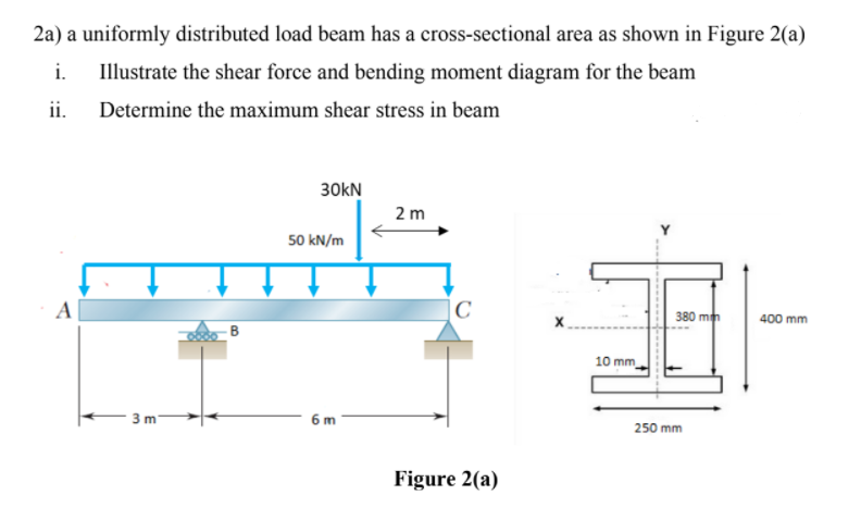
Transcribed Image Text:2a) a uniformly distributed load beam has a cross-sectional area as shown in Figure 2(a)
i.
Illustrate the shear force and bending moment diagram for the beam
ii.
Determine the maximum shear stress in beam
30KN
2 m
50 kN/m
A
C
380 mn
400 mm
10 mm
3 m
6 m
250 mm
Figure 2(a)
Expert Solution
This question has been solved!
Explore an expertly crafted, step-by-step solution for a thorough understanding of key concepts.

Step by step
Solved in 7 steps with 7 images

Knowledge Booster


Learn more about
Need a deep-dive on the concept behind this application? Look no further. Learn more about this topic, mechanical-engineering and related others by exploring similar questions and additional content below.Recommended textbooks for you
Mechanics of Materials (MindTap Course List)
Mechanical Engineering
ISBN:
9781337093347
Author:
Barry J. Goodno, James M. Gere
Publisher:
Cengage Learning
Mechanics of Materials (MindTap Course List)
Mechanical Engineering
ISBN:
9781337093347
Author:
Barry J. Goodno, James M. Gere
Publisher:
Cengage Learning