b) The simply supported beam as shown in Figure 2 is made of five planks glued together at A and B. The beam has a length of, L= 4m and carries a concentrated load P = 5 KN. The cross sectional of the beam is shown in Figure 2(b). Given the centroid of the cross section (measured from its base), 9 is 27.73 mm. i) Determine the maximum shear flow at point 4 and B, ii) Determine maximum shearing stress at point A and B, i) If the load, P is increases to 10 kN, discuss whether the joint A and B will break or not. Given the maximum shearing stress for the glhue is 0:45 kPa. (a) 10 mm 40 10 mm 30 mm 30 m 10 mm 10 mm (b) Figure 2
b) The simply supported beam as shown in Figure 2 is made of five planks glued together at A and B. The beam has a length of, L= 4m and carries a concentrated load P = 5 KN. The cross sectional of the beam is shown in Figure 2(b). Given the centroid of the cross section (measured from its base), 9 is 27.73 mm. i) Determine the maximum shear flow at point 4 and B, ii) Determine maximum shearing stress at point A and B, i) If the load, P is increases to 10 kN, discuss whether the joint A and B will break or not. Given the maximum shearing stress for the glhue is 0:45 kPa. (a) 10 mm 40 10 mm 30 mm 30 m 10 mm 10 mm (b) Figure 2

Mechanics of Materials (MindTap Course List)
9th Edition
ISBN:9781337093347
Author:Barry J. Goodno, James M. Gere
Publisher:Barry J. Goodno, James M. Gere
Chapter5: Stresses In Beams (basic Topics)
Section: Chapter Questions
Problem 5.10.10P: A hollow steel box beam has the rectangular cross section shown in the figure. Determine the maximum...

Related questions
Question
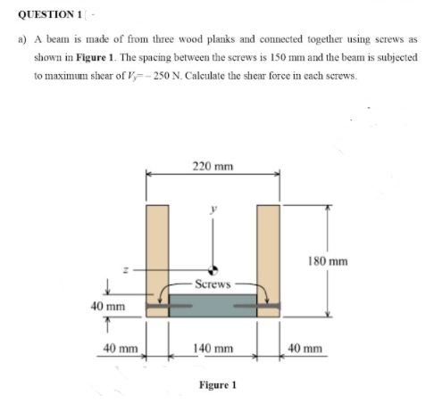
Transcribed Image Text:QUESTION 1
a) A beam is made of from three wood planks and connected together using screws as
shown in Figure 1. The spacing between the serews is 150 mm and the beam is subjected
to maximum shear of V,=- 250 N. Calculate the shear force in each screws.
220 mm
180 mm
-Screws-
40 mm
40 mm
140 mm
40 mm
Figure 1
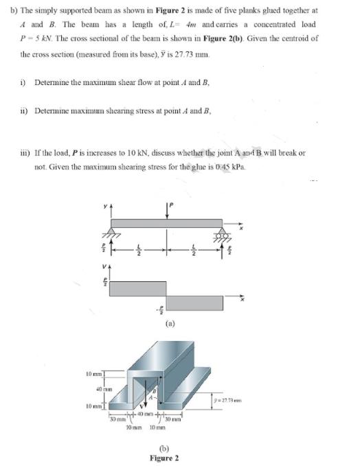
Transcribed Image Text:b) The simply supported beam as shown in Figure 2 is made of five planks glued together at
A and B. The beam has a length of, L= 4m and carries a concentrated load
P = 5 KN. The cross sectional of the beam is shown in Figure 2(b). Given the centroid of
the cross section (measured from its base), y is 27.73 mm.
i) Determine the maximum shear flow at point 4 and B,
ii) Determine maximum shearing stress at point A and B,
i) If the load, Pis inereases to 10 kN, discuss whether the joint A and B will break or
not. Given the maximum shearing stress for the ghue is 0.45 kPa.
(a)
10 mm
40 mm
9=27.13 mm
10 m
40 m-t
30 mm
10 mm
10 mm
(b)
Figure 2
Expert Solution
This question has been solved!
Explore an expertly crafted, step-by-step solution for a thorough understanding of key concepts.

This is a popular solution!

Trending now
This is a popular solution!

Step by step
Solved in 2 steps with 2 images

Knowledge Booster


Learn more about
Need a deep-dive on the concept behind this application? Look no further. Learn more about this topic, mechanical-engineering and related others by exploring similar questions and additional content below.Recommended textbooks for you
Mechanics of Materials (MindTap Course List)
Mechanical Engineering
ISBN:
9781337093347
Author:
Barry J. Goodno, James M. Gere
Publisher:
Cengage Learning
Mechanics of Materials (MindTap Course List)
Mechanical Engineering
ISBN:
9781337093347
Author:
Barry J. Goodno, James M. Gere
Publisher:
Cengage Learning