
Mechanics of Materials (MindTap Course List)
9th Edition
ISBN: 9781337093347
Author: Barry J. Goodno, James M. Gere
Publisher: Cengage Learning
expand_more
expand_more
format_list_bulleted
Concept explainers
Videos
Textbook Question
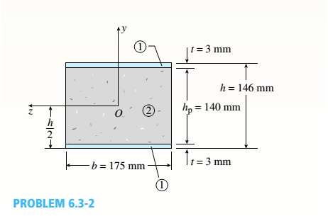
Chapter 6, Problem 6.3.2P
A sandwich beam having steel faces enclosing a plastic core is subjected to a bending moment M = 5 kN · m. The thickness of each steel face is 1 = 3 mm with modulus of elasticity E = 200 GPa, The height of the plastic core is hp= 140 mm, and its modulus of elasticity is Ep= 800 MPa. The overall dimensions of the beam are h = 146 mm and h = 175 mm.
Using the transformed-section method, determine the maximum tensile and compressive stresses in the faces and the core.
Expert Solution & Answer

Trending nowThis is a popular solution!

Students have asked these similar questions
N for Newton,
m for meter,
mm for millimeter,
N/(mm^2) for Stress,
mm^2 or m^2 for Area,
mm^4 for Moment of inertia and
Nm for bending moment. Use brackets if the power is MINUS for Example: 0.00125 N =1.25*10^(-3)N.
A beam has a bending moment of 3 kN-m applied to a section with a hollow circular cross-section of external diameter 3.4 cm and internal diameter 2.4 cm . The modulus of elasticity for the material is 210 x 109 N/m2. Calculate the radius of curvature and maximum bending stress. Also, calculate the stress at the point at 0.6 cm from the neutral axis
Solution:
(i) The moment of inertia =
ii) The radius of curvature is
(iii) The maximum bending stress is
iv) The bending stress at the point 0.6 cm from the neutral axis is
The beam cross section shown below has been proposed for a short pedestrian bridge. The cross section will consist of two pipes that are welded to a rectangular web plate. Dimensions of the cross section are:
h = 430 mm
tw = 16 mm
d = 110 mm
t = 4.8 mm
Additionally:
• The area of each pipe is A = 1586 mm2.
• The moment of inertia of the entire beam cross section about the z centroidal axis is IZ = 194710000 mm4.
If the beam will be subjected to a shear force of V = 170 kN, determine the shear stress at point K, located at yK = 70 mm below the z centroidal axis.
A beam has a bending moment of 4 kN-m applied to a section with a hollow circular cross-section of external diameter 3.3 cm and internal diameter 2.3 cm . The modulus of elasticity for the material is 210 x 109 N/m2. Calculate the radius of curvature and maximum bending stress. Also, calculate the stress at the point at 0.8 cm from the neutral axis
(i) The moment of inertia =
ii) The radius of curvature is =
(iii) The maximum bending stress is
iv) The bending stress at the point 0.8 cm from the neutral axis is
Chapter 6 Solutions
Mechanics of Materials (MindTap Course List)
Ch. 6 - A composite beam is constructed using a steel...Ch. 6 - A wood beam is strengthened using two steel plates...Ch. 6 - A composite beam consisting of fiberglass faces...Ch. 6 - A wood beam with cross-sectional dimensions 200 mm...Ch. 6 - A hollow box beam is constructed with webs of...Ch. 6 - A r o lukI f/frm f «m t ub e of ou t sid e d ia...Ch. 6 - A beam with a guided support and 10-ft span...Ch. 6 - A plastic-lined steel pipe has the cross-sectional...Ch. 6 - The cross section of a sand wie h beam consisting...Ch. 6 - The cross section of a sandwich beam consisting of...
Ch. 6 - A bimetallic beam used in a temperature-control...Ch. 6 - A simply supported composite beam 3 m long carries...Ch. 6 - A simply supported wooden I-beam with a 12-ft span...Ch. 6 - -14 A simply supported composite beam with a 3.6 m...Ch. 6 - -15 A composite beam is constructed froma wood...Ch. 6 - A wood beam in a historic theater is reinforced...Ch. 6 - Repeat Problem 6.2-1 but now assume that the steel...Ch. 6 - Repeat Problem 6.2-17 but now use a...Ch. 6 - A sandwich beam having steel faces enclosing a...Ch. 6 - A wood beam 8 in. wide and 12 in. deep (nominal...Ch. 6 - A simple beam of span length 3.2 m carries a...Ch. 6 - A simple beam that is 18 ft long supports a...Ch. 6 - The composite beam shown in the figure is simply...Ch. 6 - The cross section of a beam made of thin strips of...Ch. 6 - Consider the preceding problem if the beam has...Ch. 6 - A simple beam thai is IS ft long supports a...Ch. 6 - The cross section of a composite beam made of...Ch. 6 - A beam is constructed of two angle sections, each...Ch. 6 - The cross section of a bimetallic strip is shown...Ch. 6 - A W 12 x 50 steel wide-flange beam and a segment...Ch. 6 - A reinforced concrete beam (see figure) is acted...Ch. 6 - A reinforced concrete T-beam (see figure) is acted...Ch. 6 - A reinforced concrete slab (see figure) is...Ch. 6 - A wood beam reinforced using two channels is...Ch. 6 - A wood beam reinforced by an aluminum channel...Ch. 6 - A beam with a rectangular cross section supports...Ch. 6 - A wood beam with a rectangular cross section (see...Ch. 6 - Solve the preceding problem for the following...Ch. 6 - A simply supported wide-flange beam of span length...Ch. 6 - Solve the preceding problem using the fol...Ch. 6 - A wood cantilever beam with a rectangular cross...Ch. 6 - Solve the preceding problem for a cantilever beam...Ch. 6 - A 2-m-long cantilever beam is constructed using a...Ch. 6 - A wood beam AB with a rectangular cross section (4...Ch. 6 - A steel beam of I-section (see figure) is simply...Ch. 6 - A cantilever beam with a wide-flange cross section...Ch. 6 - Solve the preceding problem using a W 310 x 129...Ch. 6 - A cantilever beam of W 12 × 14 section and length...Ch. 6 - A cantilever beam built up from two channel...Ch. 6 - A built-Lip I-section steel beam with channels...Ch. 6 - Repeat Problem 6.4-14 but use the configuration of...Ch. 6 - A beam with a channel section is subjected to a...Ch. 6 - A beam with a channel section is subjected to a...Ch. 6 - An angle section with equal legs is subjected to a...Ch. 6 - An angle section with equal legs is subjected to a...Ch. 6 - A beam made up all woun equal leg angles is...Ch. 6 - The Z-section of Example D-7 is subjected to M = 5...Ch. 6 - The cross section of a steel beam is constructed...Ch. 6 - The cross section of a steel beam is shown in the...Ch. 6 - A beam with a semicircular cross section of radius...Ch. 6 - .10 A built-up bourn supporting a condominium...Ch. 6 - Asteelpost (E = 30 × 106 psi) having thickness t =...Ch. 6 - A C 200 x 17.1 channel section has an angle with...Ch. 6 - A cold-formed steel section is made by folding a...Ch. 6 - A simple beam with a W 10 x 30 wide-flange cross...Ch. 6 - Solve the preceding problem for a W 250 × 44.8...Ch. 6 - A beam of wide-flange shape, W 8 x 28, has the...Ch. 6 - Solve the preceding problem for a W 200 × 41,7...Ch. 6 - Calculate the distance e from the cent crime of...Ch. 6 - Calculate the distance e from the centerline of...Ch. 6 - The cross section of an unbalanced wide-flange...Ch. 6 - The cross section of an unbalanced wide-flange...Ch. 6 - The cross section of a channel beam with double...Ch. 6 - The cross section of a slit circular tube of...Ch. 6 - The cross section of a slit square tube of...Ch. 6 - The cross section of a slit rectangular tube of...Ch. 6 - A U-shaped cross section of constant thickness is...Ch. 6 - Derive the following formula for the distance e...Ch. 6 - Derive the following formula for the distance e...Ch. 6 - The cross section of a sign post of constant...Ch. 6 - A cross section in the shape of a circular arc of...Ch. 6 - Determine the shape factor f for a cross section...Ch. 6 - (a) Determine the shape factor/for a hollow...Ch. 6 - A propped cantilever beam of length L = 54 in....Ch. 6 - A steel beam of rectangular cross section is 40 mm...Ch. 6 - .5 Calculate the shape factor j for the...Ch. 6 - Solve the preceding problem for a wide-flange beam...Ch. 6 - Determine the plastic modulus Z and shape...Ch. 6 - Prob. 6.10.8PCh. 6 - Prob. 6.10.9PCh. 6 - Prob. 6.10.10PCh. 6 - A hollow box beam with height h = 16 in,, width h...Ch. 6 - Solve the preceding problem for a box beam with...Ch. 6 - A hollow box beam with height h = 9.5 in., inside...Ch. 6 - Solve the preceding problem for a box beam with...Ch. 6 - The hollow box beam shown in the figure is...Ch. 6 - Prob. 6.10.16PCh. 6 - Prob. 6.10.17PCh. 6 - A singly symmetric beam with a T-section (see...Ch. 6 - A wide-flange beam with an unbalanced cross...Ch. 6 - .20 Determine the plastic moment Mpfor beam having...
Knowledge Booster


Learn more about
Need a deep-dive on the concept behind this application? Look no further. Learn more about this topic, mechanical-engineering and related others by exploring similar questions and additional content below.Similar questions
- .2 A ligmio.irc ii supported by two vorlical beams consistins: of thin-walled, tapered circular lubes (see ligure part at. for purposes of this analysis, each beam may be represented as a cantilever AB of length L = 8.0 m subjected to a lateral load P = 2.4 kN at the free end. The tubes have a constant thickness ; = 10.0 mm and average diameters dA = 90 mm and dB = 270 mm at ends A and B, re s pec lively. Because the thickness is small compared to the diameters, the moment of inerlia at any cross section may be obtained from the formula / = jrrf3;/8 (see Case 22, Appendix E); therefore, the section modulus mav be obtained from the formula S = trdhlA. (a) At what dislance A from the free end docs the maximum bending stress occur? What is the magnitude trllul of the maximum bending stress? What is the ratio of the maximum stress to the largest stress (b) Repeat part (a) if concentrated load P is applied upward at A and downward uniform load q {-x) = 2PIL is applied over the entire beam as shown in the figure part b What is the ratio of the maximum stress to the stress at the location of maximum moment?arrow_forwardA cantilever beam of a length L = 2.5 ft has a rectangular cross section {b = 4in,, h = Sin,) and modulus E = 10,000 ksi. The beam is subjected to a linearly varying distributed load with a peak intensity qQ= 900 lb/ft. Use the method of superposition and Cases 1 and 9 in Table H-l to calculate the deflection and rotation at B.arrow_forwardA simple beam with a W 10 x 30 wide-flange cross section supports a uniform load of intensity q = 3.0 kips/ft on a span of length L = 12 ft (sec figure). The dimensions of the cross section are q = 10.5 in., b = 5.81 in., t1= 0.510 in., and fw = 0.300 in. Calculate the maximum shear stress tjuly on cross section A—A located at distance d = 2.5 ft from the end of the beam. Calculate the shear stress rat point Bon the cross section. Point B is located at a distance a = 1.5 in. from the edge of the lower flange.arrow_forward
- A thin-walled aluminum tube of rectangular cross section (sec fig me) has a centerline dimensions b = 6.0 in. and b = 4.0 in. The wall thickness t is constant and equal to 0.25 in. Determine the shear stress in the tube due to a torque T = 15 kip-in. Determine the angle of twist (in degrees) if the length L of the tube is 50 in. and the shear modulus G is 4.0 x 10⁶ psi.arrow_forwardThe cross section of a sand wie h beam consisting of aluminum alloy faces and a foam core is shown in the figure. The width b of the beam is 8.0 in, the thickness I of the faces is 0.25 in., and the height hcof the core is 5.5 in. (total height h = 6.0 in). The moduli of elasticity are 10.5 × 10⁶ psi for the aluminum faces and 12.000 psi for the foam core. A bending moment M = 40 kip-in. acts about the z axis. Determine the maximum stresses in the faces and the core using (a) the general theory for composite beams and (b) the approximate theory for sandwich beams.arrow_forwardSolve the preceding problem using the fol low-data: W 8 × 21 section, L = 84 in., P = 4.5 kips, a = 22.5°.arrow_forward
- The cross section of a rectangular beam having a width b and height h is shown in part a of the figure. For reasons unknown to the beam designer, it is planned to add structural projections of width b/9 and height d/9 the top and bottom of the beam (see part b of the figure). For what values of d is the bending-moment capacity of the beam increased? For what values is it decreased?arrow_forwardDetermine the shape factor f for a cross section in the shape of a double trapezoid having the dimensions shown in the figure. Also, check your result for the special cases of a rhombus (b1= 0) and a rectangle (b1= b2).arrow_forwardA simple beam AB of length L and height h (see figure) is heated in such a manner that the temperature difference 7= T{between the bottom and top of the beam is proportional to the distance from support A: that is, assume the temperature difference varies linearly along the beam: T2- Tt= Tax in which 7"0 is a constant having units of temperature (degrees) per unit distance. Determine the maximum deflection SW9Xof the beam, Repeat for a quadratic temperature variation along the beam, so T2+T1= Taxarrow_forward
- The tapered cantilever beam AB shown in the figure has a thin-walled, hollow circular cross sections of constant thickness t. The diameters at the ends A and B are dAand dB= 2dA, respectively. Thus, the diameter d and moment of inertia / at distance x from the free end are, respectively, in which IAis the moment of inertia at end A of the beam. Determine the equation of the deflection curve and the deflection 8 Aat the free end of the beam due to the load P.arrow_forwardA tapered cantilever beam A B supports a concentrated load P at the free end (see figure). The cross sections of the beam are rectangular with constant width A, depth d Aat support A, and depth ds= ^dJ2 at the support. Thus, the depth d and moment of inertia / at distance x from the free end are, respectively, in which / 4 is the moment of inertia at end A of the beam. Determine the equation of the deflection curve and the deflection S 4at the free end of the beam due to the load P.arrow_forwardA beam has a bending moment of 3.5 kN-m applied to a section with a hollow circular cross-section of external diameter 3.7 cm and internal diameter 2.2 cm . The modulus of elasticity for the material is 210 x 109 N/m2. Calculate the radius of curvature and maximum bending stress. Also, calculate the stress at the point at 0.6 cm from the neutral axis (i) The moment of inertia = ii) The radius of curvature is (iii) The maximum bending stress is iv) The bending stress at the point 0.6 cm from the neutral axis is Answer and unit for part 4arrow_forward
arrow_back_ios
SEE MORE QUESTIONS
arrow_forward_ios
Recommended textbooks for you
 Mechanics of Materials (MindTap Course List)Mechanical EngineeringISBN:9781337093347Author:Barry J. Goodno, James M. GerePublisher:Cengage Learning
Mechanics of Materials (MindTap Course List)
Mechanical Engineering
ISBN:9781337093347
Author:Barry J. Goodno, James M. Gere
Publisher:Cengage Learning
Everything About COMBINED LOADING in 10 Minutes! Mechanics of Materials; Author: Less Boring Lectures;https://www.youtube.com/watch?v=N-PlI900hSg;License: Standard youtube license