3-4. By the method of section, compute the bar forces in the lettered bars of the trusses shown in Fig. 3-36. 12 ft ▼20* 5 at 16 ft 80 ft 20 (a)
3-4. By the method of section, compute the bar forces in the lettered bars of the trusses shown in Fig. 3-36. 12 ft ▼20* 5 at 16 ft 80 ft 20 (a)

Mechanics of Materials (MindTap Course List)
9th Edition
ISBN:9781337093347
Author:Barry J. Goodno, James M. Gere
Publisher:Barry J. Goodno, James M. Gere
Chapter2: Axially Loaded Members
Section: Chapter Questions
Problem 2.8.3P

Related questions
Question
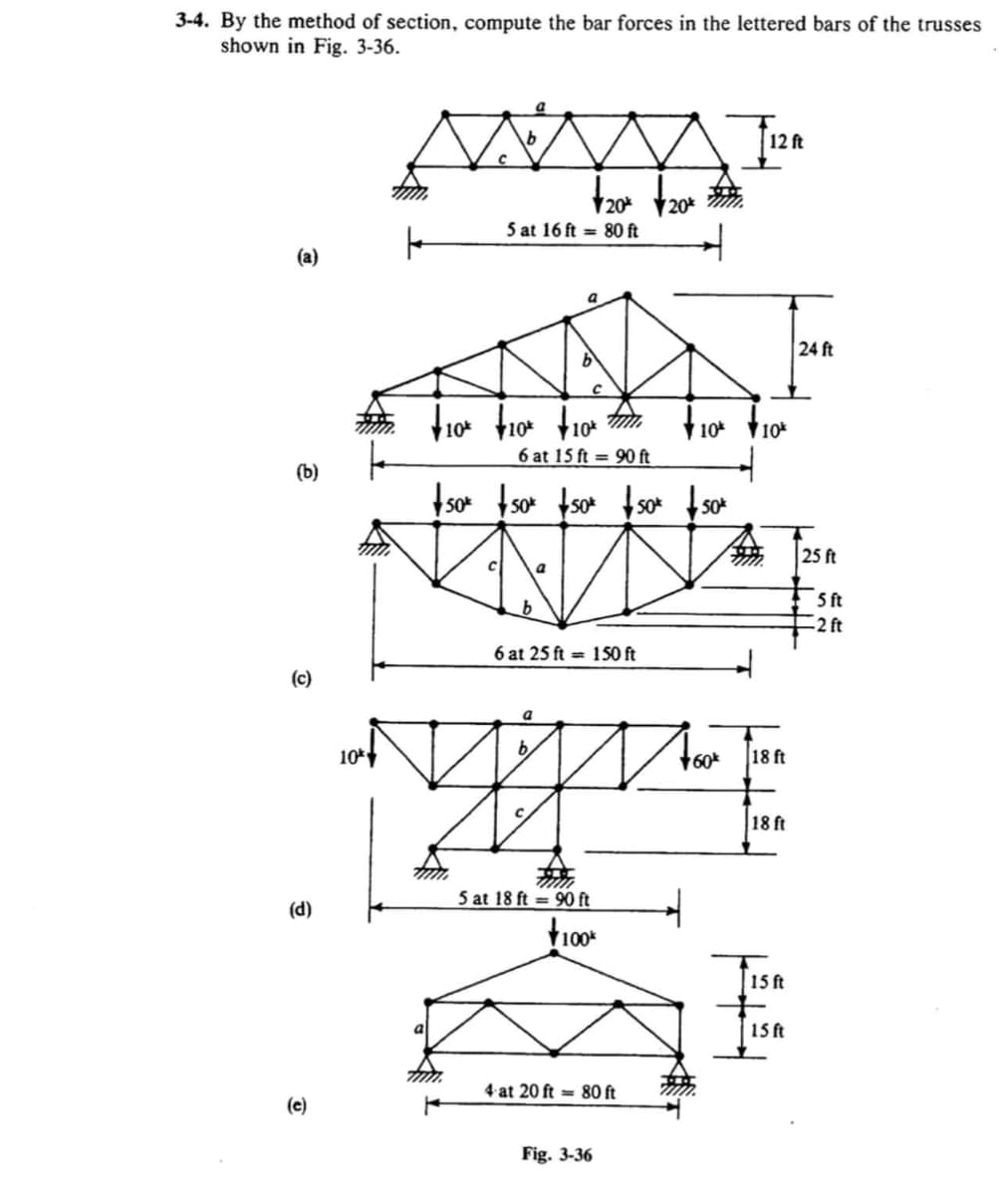
Transcribed Image Text:3-4. By the method of section, compute the bar forces in the lettered bars of the trusses
shown in Fig. 3-36.
12 ft
V20* 20*
5 at 16 ft = 80 ft
(a)
a
24 ft
10
10
10%
6 at 15 ft = 90 ft
(b)
Iso tso tsot f s*
so* so*
25 ft
5 ft
-2 ft
6 at 25 ft = 1S0 ft
(c)
10
b,
18 ft
18 ft
5 at 18 ft = 90 ft
(d)
15ft
15 ft
4 at 20 ft = 80 ft
(e)
Fig. 3-36
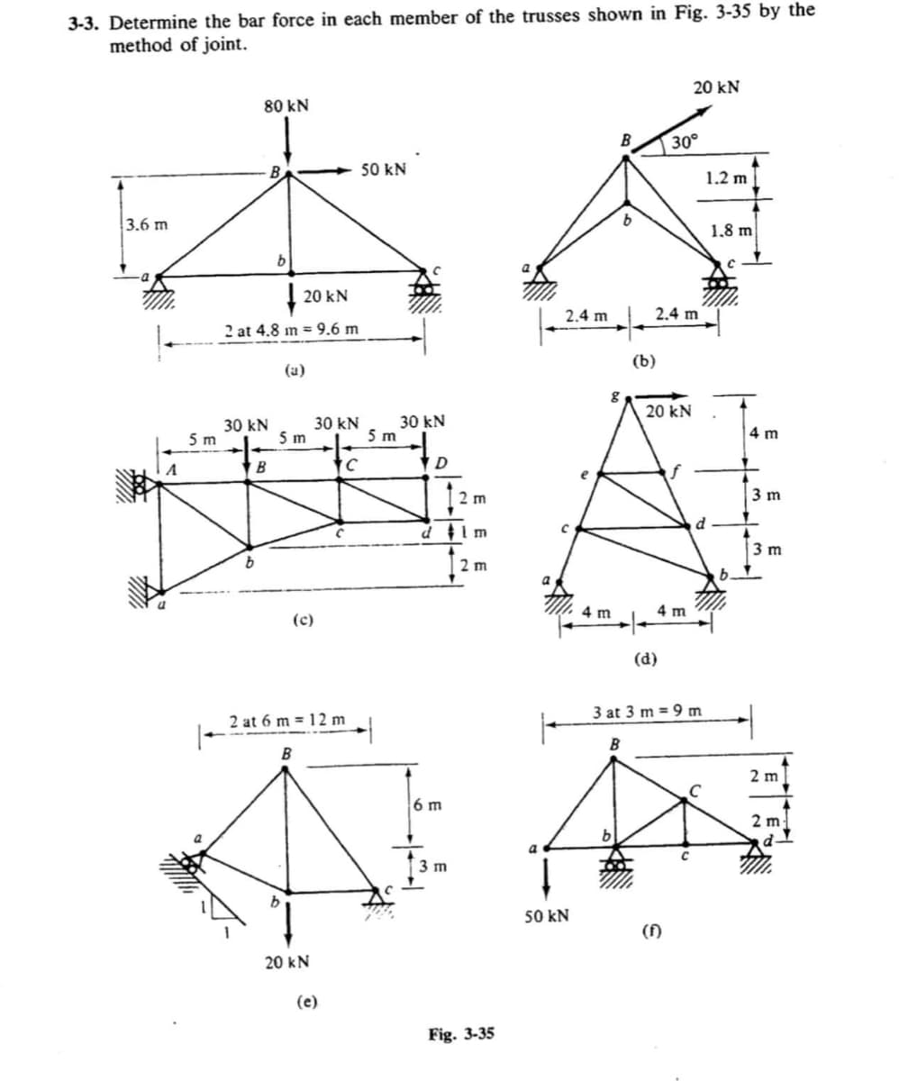
Transcribed Image Text:3-3. Determine the bar force in each member of the trusses shown in Fig. 3-35 by the
method of joint.
20 kN
80 kN
30°
50 kN
1.2 m
3.6 m
1,8 m
20 kN
2.4 m
2.4 m
2 at 4.8 m = 9.6 m
(b)
(a)
20 kN
30 kN
5 m
30 kN
30 kN
5 m
4 m
5 m
to
B
2 m
3 m
m
3 m
4 m
4 m
(c)
(d)
3 at 3 m = 9 m
2 at 6 m = 12 m
|-
2 m
6 m
2 m
3 m
50 kN
()
20 kN
(e)
Fig. 3-35
E E E
Expert Solution
This question has been solved!
Explore an expertly crafted, step-by-step solution for a thorough understanding of key concepts.

Step by step
Solved in 3 steps with 3 images

Recommended textbooks for you
Mechanics of Materials (MindTap Course List)
Mechanical Engineering
ISBN:
9781337093347
Author:
Barry J. Goodno, James M. Gere
Publisher:
Cengage Learning
Mechanics of Materials (MindTap Course List)
Mechanical Engineering
ISBN:
9781337093347
Author:
Barry J. Goodno, James M. Gere
Publisher:
Cengage Learning