solve for the force in members eF and EG for the truss shown in Fig. P-4-3.14
solve for the force in members eF and EG for the truss shown in Fig. P-4-3.14

Mechanics of Materials (MindTap Course List)
9th Edition
ISBN:9781337093347
Author:Barry J. Goodno, James M. Gere
Publisher:Barry J. Goodno, James M. Gere
Chapter1: Tension, Compression, And Shear
Section: Chapter Questions
Problem 1.3.10P: Find support reactions at 4 and Band then use the method of joints to find all member forces. Let b...

Related questions
Question
4-3.15. solve for the force in members eF and EG for the truss shown in Fig. P-4-3.14
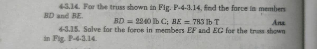
Transcribed Image Text:4-3.14. For the truss shown in Fig. P-4-3.14, find the force in members
BD and BE.
BD=2240 lb C; BE = 783 lb T
4-3.15. Solve for the force in members EF and EG for the truss shown
Ans.
%3D
%3D
in Fig. P-4-3.14.
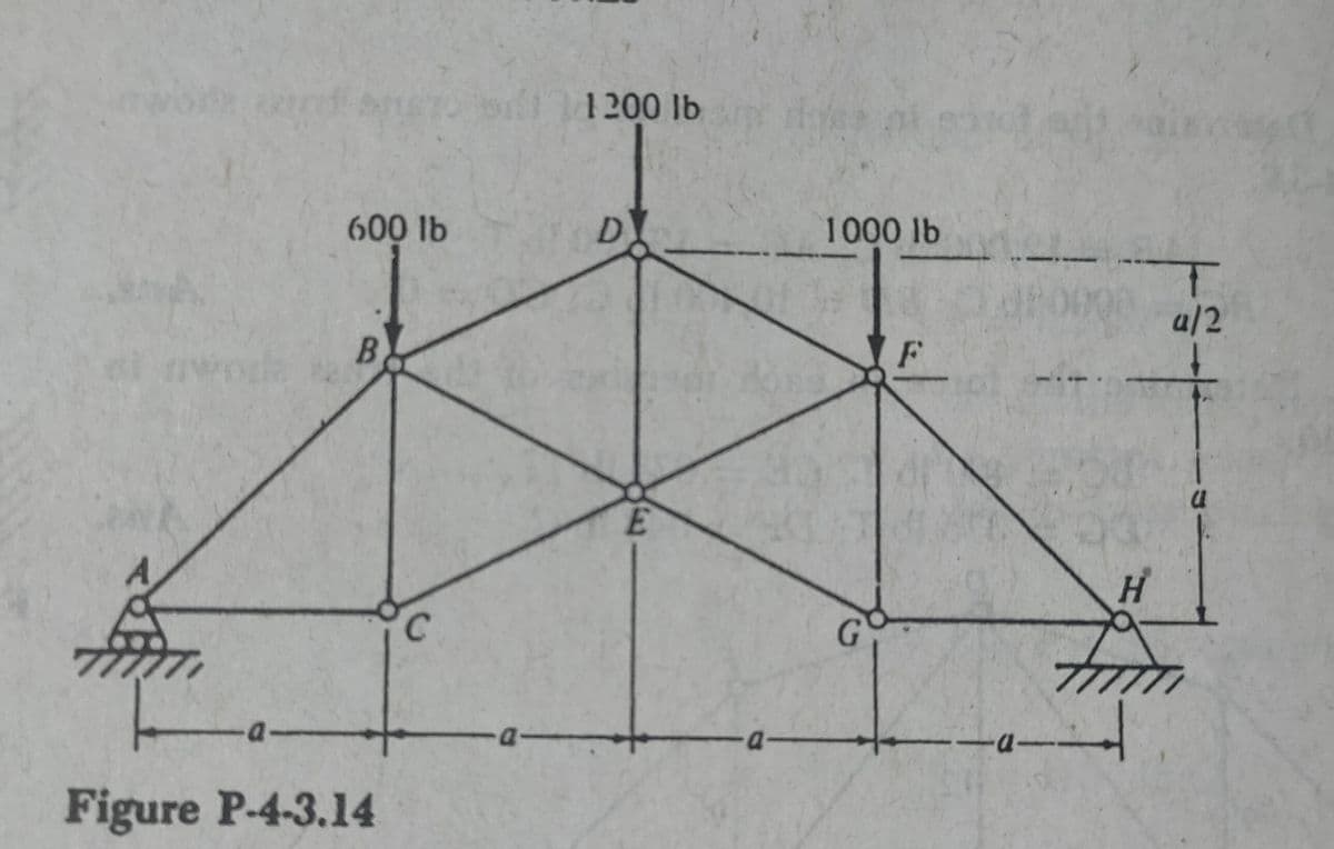
Transcribed Image Text:b 1200 lb
600 lb
D
1000 lb
a/2
B.
E.
A.
Hi
C.
Figure P-4-3.14
Expert Solution
This question has been solved!
Explore an expertly crafted, step-by-step solution for a thorough understanding of key concepts.

This is a popular solution!

Trending now
This is a popular solution!

Step by step
Solved in 2 steps with 1 images

Knowledge Booster


Learn more about
Need a deep-dive on the concept behind this application? Look no further. Learn more about this topic, mechanical-engineering and related others by exploring similar questions and additional content below.Recommended textbooks for you
Mechanics of Materials (MindTap Course List)
Mechanical Engineering
ISBN:
9781337093347
Author:
Barry J. Goodno, James M. Gere
Publisher:
Cengage Learning
Mechanics of Materials (MindTap Course List)
Mechanical Engineering
ISBN:
9781337093347
Author:
Barry J. Goodno, James M. Gere
Publisher:
Cengage Learning