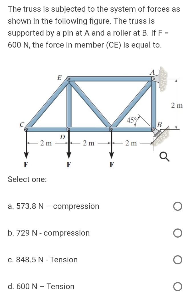
The truss is subjected to the system of forces as shown in the following figure. The truss is supported by a pin at A and a roller at B. If F = 600 N, the force in member (CE) is equal to.
Q: Q.2) For the system and load shown in figure, Determine the reaction forces of bearing at A and B,…
A: Given
Q: Q.2) For the system and load shown in figure, Determine the reaction forces of bearing at A and B,…
A: The coordinates of points C & D Let the tension in the cable be T The reaction at the bearing A…
Q: The simple truss is loaded by a system of forces as shown in the figure. The truss is supported by a…
A: (1) Given-
Q: Q2/ In equilibrium position shown in figure below. The uniform bar (AB) has a mass of (50 kg) and…
A:
Q: Problem 2. For the Plane frame shown in figure, determine the axial force in cord (DE) and the…
A:
Q: The system with two pin supports, and having an internal pin at C, is subject to two horizontal…
A:
Q: The truss is subjected to the system of forces as shown in the following figure. The truss is…
A: Given: The truss is shown below:
Q: The simple truss is loaded by a system of forces as shown in the figure. The truss is supported by a…
A: Given, P=800 lb
Q: The vertical force P of magnitude 100 kN is applied to the frame shown in the figure. Resolve P into…
A: P = 100 kN
Q: 1. The frame shown in the figure is hinged at E and roller supported at A. Determine the horizontal…
A:
Q: The reactions at the rigid supports at A and B for the bar loaded as shown in the figure are…
A: Given : P = 10 KN To find : reactions at the rigid supports at A and B
Q: Determine the internal forces at point D of the frame shown in the figure.
A: According to the details provided in the question, we need to calculate internal forces at point D
Q: 4. For the frame shown in the figure, determine the horizontal and vertical components of the hinge…
A:
Q: Find the forces in members CE and CF in the figure below using the method of sections. Enter your…
A:
Q: Q2: The vertical force P of magnitude 100 kN is applied to the frame shown in the Figure below.…
A: Given ; force = p = 100 kN (down wards) varicalThere are two numbers AB & AC of trusswe have to…
Q: Q2) 4 m 2 m 2 m The frame as shown in the Figure consist of two members AC and BE. Calculate the…
A: FREE BODY DIAGRAM is a diagram of the system which represents all the forces acting on the system.…
Q: 3a)Two cylinders each of diameter 100 mm and each weighing 200 N are placed as shown in figure…
A:
Q: The truss is subjected to the system of forces as shown in the following figure. The truss is…
A:
Q: The truss is subjected to the system of forces as shown in the following figure. The truss is…
A:
Q: Q.2) For the system and load shown in figure, Determine the reaction forces of bearing at A and B,…
A: The coordinates of points C and D from the figure are, Let the tension in the cable CD be T The…
Q: A Block of weight 114 N is suspended with the help of a string. The block is pulled by a horizontal…
A:
Q: The truss is subjected to the system of forces as shown in the following figure. The truss is…
A: Given data :- At A = 6 KN At E = 8 KN Find :- The force in Member AE = ?
Q: The rigid bars AB and CD shown in Figure below are supported by pins at A and C and the two rods.…
A: For the aluminum cable, Length of the Aluminum, LAl=2m=2000 mm Area of the aluminum, AAl=500mm2…
Q: The truss is subjected to the system of forces as shown in the following figure. The truss is…
A:
Q: The truss is subjected to the system of forces as shown in the following figure. The truss is…
A:
Q: The simple truss is loaded by a system of forces as shown in the figure. The truss is supported by a…
A: Given data: The load P1 is P1 = 40 kN. The load P2 is P2 = 20 kN. The distance between FE is x =…
Q: Cable GH holds the truss composed of equilateral triangles in the position shown in the figure…
A: A pin support will exert both horizontal and vertical components of reaction as the reaction forces.…
Q: For the frame shown in the figure a smooth pulley attached to the frame rests on a cable at B. (You…
A: a.Two force members Two force members are those members which are pinned or hinged at both the…
Q: Q1/ The rigid bars AB and CD shown in Figure below are supported by pins at A and C and the two…
A:
Q: The light boom AB is attached to a vertical wall by a ball and socket joint at A and supported by…
A: Given that The force P→ is 19i^-10j^ KNThe coordinates from the figure are:A 2,0,-3; B (0,6,0); C…
Q: The truss is subjected to the system of forces as shown in the following figure. The truss is…
A:
Q: find the value of R1
A: Given: weight of the Carriage (W1) =480 lb Weight of the ladder (W2) =240 lb P= 180 lb Distance…
Q: The figure shows a setup where when the member AB is horizontal and the unstretched aluminum bar…
A:
Q: b) For the truss in the figure below, determine the zero-force members and give a short explanation…
A:
Q: A beam is loaded and supported as shown, where W1-818 lb/ft, w2=334 lb/ft, a=3.5 ft, b-4.0 ft, and…
A:
Q: The pole is subjected to the two forces shown in Figure Ql. Determine the support reaction A with…
A:
Q: The roof truss shown in the figure has fixed support at F and roller support at A. Find the reaction…
A:
Q: The frame shown in Figure below consists of two members (BC and ABD) and it is subjected by the…
A:
Q: The simple truss is loaded by a system of forces as shown in the figure. The truss is supported by a…
A: Given data: The magnitude of the force P acting on the truss is P = 800 lb.
Q: 3. The system of chords is knotted as shown in figure below, carry the weights: 300lb & 400 lb.…
A:
Q: The truss is subjected to the system of forces as shown in the following figure. The truss is…
A:
Q: The truss is subjected to the system of forces as shown in the following figure. The truss is…
A: The free body diagram of the truss is given below,
Q: In the figure shown, the frame is supported using a hinge in point A and a røler in point B. The…
A:
Q: The truss is subjected to the system of forces as shown in the following figure. The truss is…
A: The free body diagram at point E is as follows.
Q: For the suspended load F = 637lb in the figure. Find the magnitude of the reaction of the patella at…
A: Given data, Suspended load, F= 637 lb The coordinates of O = (0, 0, 0) The coordinates of A = (8, 6,…
Q: For the frame shown in the below Figure, determine the horizontal and vertical components of the…
A: Given data given figure
Q: The truss is subjected to the system of forces as shown in the following figure. The truss is…
A: The free body diagram at the point E is as follows: Calculate the vertical force at the joint E is…
Q: Problem 2. For the Plane frame shown in figure, determine the axial force in cord (DE) and the…
A: Moment (M) at point D: 29 kN.m Vertical Load at D: 7 kN Horizontal load on member BE: 10.5 kN
Q: The frame shown in the figure is supported by a hinge at E and a roller at D. Compute the horizontal…
A:
Trending now
This is a popular solution!
Step by step
Solved in 2 steps with 1 images
- The roof over a concourse at an airport is supported by the use of pretensioned cables. At a typical joint in the roof structure, a strut AB is compressed by the action of tensile forces Fin a cable that makes an angle = 75° with the strut (see figure and photo). The strut is a circular tube of steel (E = 30,000 ksi) with outer diameter d2= 2.5 in. and inner diameter d1= 2.0 in. The strut is 5.75 ft long and is assumed to be pin-connected at both ends. Using a factor of safety n = 2.5 with respect to the critical load, determine the allowable force F in the cable.Find support reactions at 4 and Band then use the method of joints to find all member forces. Let b = 3 m and P = 80 kN.A truss ABC supports a load W at joint B, as shown in the figure. The length L, of member Aß is fixed, but the length of strut BC varies as the angle is changed. Strut BC has a solid circular cross section. Joint B is restrained against displacement perpendicular to the plane of the truss. Assuming that collapse occurs by Etiler buckling of the strut determine the angle for minimum weight of the strut.
- A crane boom of mass 450 leg with its center of mass at C is stabilized by two cables AQ and BQ (Ae= 304 mm2 for each cable) as shown in the figure. A load P = 20 KN is supported at point D. The crane boom lies in the y-z plane. (a) Find the tension forces in each cable: TAQand TBQ(kN}. Neglect the mass of the cables, but include the mass of the boom in addition to load P. (b) Find the average stress (s) in each cable.An elevated jogging track is supported at intervals by a wood beam AB (L = 7.5 ft) that is pinned at A and supported by steel rod BC and a steel washer at B. Both the rod (dBC= 3/16 in.) and the washer (dB= 1.0 in.) were designed using a rod tension force of TBC=415 lb. The rod was sized using a factor of safely of 3 against reaching the ultimate stress tru— 60 ksi. An allowable bearing stress sba= 565 psi was used to size the washer at B. A small platform HF is suspended below a section of the elevated track to support some mechanical and electrical equipment. The equipment load is uniform load q = 50 lb/ft and concentrated load WE= 175 lb at mid-span of beam HF. The plan is to drill a hole through beam ABaX £land install the same rod (dBC) and washer) dB) at both D and F to support beam HF. (a) Use s and to check the proposed design for rod DF and washer d,: are they acceptable? (b) Re-check the normal tensile stress in rod BC and bearing stress at 8 if either is inadequate under the additional load from platform HF. Re-design them to meet the original design criteria.A plane frame with a pin support at A and roller supports at C and £ has a cable attached at E. which runs over Frictionless pulleys al D and B (see figure). The cable force is known to be 400 N. There is a pin connection just Lo the left of joint C. (a) Find reactions at supports^, C, and E. (b) Find internal stress, resultants N, V, and M just to the right of joint C. (c) Find resultant force in the pin near C.
- A steel cable with a nominal diameter of 25 mm (see Table 2-1) is used in a construction yard to lift a bridge section weighing 38 kN. as shown in the figure. The cable has an effective modulus of elasticity E = 140 GPa. (a) If the cable is 14 m long, how much will it stretch when the load is picked up? (b) If the cable is rated for a maximum load of 70 kN, that is the factor of safety with respect to failure of the cable?The truss ABC shown in the figure supports a vertical load W at joint B. Each member is a slender circular steel pipe (E = 30,000 ksi) with an outside diameter of 4 in. and wall thickness 0.25 in. The distance between supports is 23 ft. Joint B is restrained against displacement perpendicular to the plane of the truss. Determine the critical value Wcr of the load.A vertical pole of aluminum is fixed at the base and pulled at the top by a cable having a tensile force T(see figure). The cable is attached at the outer edge of a stiffened cover plate on top of the pole and makes an angle a = 20° at the point of attachment. The pole has length a = 2.5 m and a hollow circular cross section with an outer diameter d2= 280 mm and inner diameter d1= 220 mm. The circular cover plate has diameter 1.5d2 Determine the allowable tensile force Tallow in the cable if the allowable compressive stress in the aluminum pole is 90 MPa.
- A 150-lb rigid bar AB. with friction less rollers al each end. is held in the position shown in the figure by a continuous cable CAD. The cable is pinned at C and D and runs over a pulley at A. (a) Find reactions at supports A and B. (b) Find the force in the cable.A large precast concrete panel for a warehouse is raised using two sets of cables at two lift lines, as shown in the figure part a. Cable 1 has a length L1 = 22 Ft, cable 2 has a length L2= 10 ft, and the distance along the panel between lift points Band D is d = 14 ft (see figure part b). The total weight of the panel is W = 85 kips. Assuming the cable lift Forces F at each lift line are about equal, use the simplified model of one half of the panel in figure part b to perform your analysis for the lift position shown. Find the required cross-sectional area AC of the cable if its breaking stress is 91 ksi and a factor of safety of 4 with respect to failure is desired.Solve the preceding problem if the mass of the tailgate is MT— 11 kg and that of the crate is hic— 6S kg. Use dimensions H = 305 mm, L = 406 mm, dc= 460 mm, and dT= 350 mm. The cable cross-sectional area is At= 11.0 mm'. (a) Find the tensile Force T and normal stress T in each cable. (b) IF each cable elongates