3 V 6 uF HIH 8V in 5 ohm 5 ohm 3 ohm Calculate the current passing through each resistor when the capacitor in the given circuit is fully charged. What is the maximum charge on the capacitor? 4 V
3 V 6 uF HIH 8V in 5 ohm 5 ohm 3 ohm Calculate the current passing through each resistor when the capacitor in the given circuit is fully charged. What is the maximum charge on the capacitor? 4 V

Delmar's Standard Textbook Of Electricity
7th Edition
ISBN:9781337900348
Author:Stephen L. Herman
Publisher:Stephen L. Herman
Chapter24: Resistive-inductive-capacitive Parallel Circuits
Section: Chapter Questions
Problem 1RQ: An AC circuit contains a 24 resistor, a 15.9-mH inductor, and a 13.3F capacitor connected in...

Related questions
Question
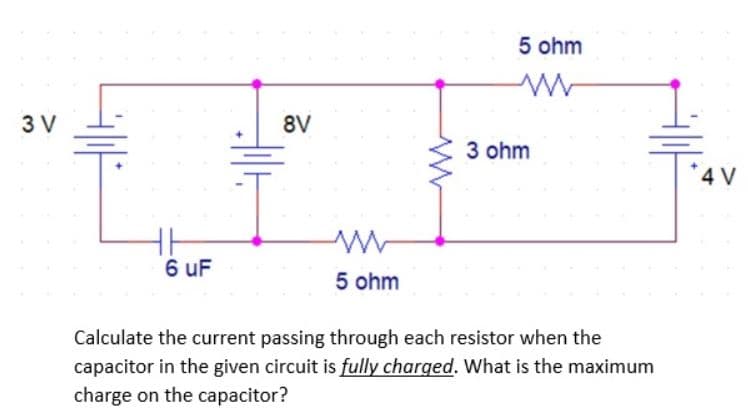
Transcribed Image Text:3 V
6 uF
HIH
8V
in
5 ohm
5 ohm
3 ohm
Calculate the current passing through each resistor when the
capacitor in the given circuit is fully charged. What is the maximum
charge on the capacitor?
4 V
Expert Solution
This question has been solved!
Explore an expertly crafted, step-by-step solution for a thorough understanding of key concepts.

Step by step
Solved in 3 steps with 2 images

Recommended textbooks for you
Delmar's Standard Textbook Of Electricity
Electrical Engineering
ISBN:
9781337900348
Author:
Stephen L. Herman
Publisher:
Cengage Learning

Electricity for Refrigeration, Heating, and Air C…
Mechanical Engineering
ISBN:
9781337399128
Author:
Russell E. Smith
Publisher:
Cengage Learning
Delmar's Standard Textbook Of Electricity
Electrical Engineering
ISBN:
9781337900348
Author:
Stephen L. Herman
Publisher:
Cengage Learning
Electricity for Refrigeration, Heating, and Air C…
Mechanical Engineering
ISBN:
9781337399128
Author:
Russell E. Smith
Publisher:
Cengage Learning