3. The load flow data for a three-bus system is given below. Taking bus 1 as the slack bus, determine the voltages of the various buses at the end of first iteration starting with a flat voltage profile for all
Q: Design a synchronous counter that count 0,1,2,3,4,5,6,7,8,9,0 ... using Karnaugh map.
A: Counting Sequence is 0-1-2-3-4-5-6-7-8-9-0 repeats on,, This is MOD-10 Counter.
Q: In power flow studies,if a network consists of a generator bus which elements of Jacobian Matrix…
A: The generator bus is also called PV or voltage controlled bus. The quantities specified for such…
Q: Why the time consumption is more for ZBus building compare to YBus ? as
A: Zbus matrix is called as the impedance matrix and the Ybus matrix is called as the admittance…
Q: Why the time consumption is more for ZBus building as compare to YBus ?
A: ZBUS matrix is also known as the impedance matrix which is formed based on the impedance value YBUS…
Q: The single line diagram of figure below shows a generator connected through parallel transmission…
A: when a 3 phase fault occurs at any of the middles of one of the transmission line then the…
Q: Explain the difference between AC versus DC transmission line design, reliability, applications and…
A:
Q: 1. List out how does a priority method varies from dynamic programming method in Unit commitment…
A: NOTE: We’ll answer the first question since the exact one wasn’t specified. Please submit a new…
Q: What are the wind turbine losses? How to minimize these losses? What is the role of SCADA system in…
A: Wind turbine losses: There will be electrical losses practised between the low voltage terminals of…
Q: Find the unkowns of each bus by using Gauss Siedel Method
A: Formulate YBUS y12=1Z12=10.02+j0.04=10-j20y13=1Z13=10-j30y23=1Z23=10.0125+j0.025=16-j32…
Q: Develop the bus admittance matrix of the following two-bus network.
A: Given two bus system with two branches 2 and 0.5 ohm mutual impedance is 0.3 ohm then we find the…
Q: In paralleling operation, the generator with the least droop took a greater share of the increase in…
A: First we will draw characteristics of genetor with two diffrent droping charecteristics, using…
Q: Q1/For 14 bus IEEE System in normal condition; why and what difference between results power flow…
A: Power flow analysis, The power flow or load flow is the analysis of the power flow of the system.…
Q: What are the advantages and disadvantages of the series hybrid vehicle topology? Please give brief…
A: Hybrid electric vehicles or HEVs merge internal combustion engines with electric motors, offering…
Q: In sectionalized single bus bar system, each section can be operated independent of the other…
A: In a sectionalized single bus bar system, each section can be operated independently of each other…
Q: "In paralleling operation, the generator with the least droop took a greater share of the increase…
A: In this question we need to verify the given statement is true or false
Q: 1) The Bus Interface Unit (BIU) construction?
A: according to guidelines, we need to solve only first question.
Q: 4. A two-bus power system bus admittance matrix is bus -j9 j3 j3 -j8 53] P per unit. Suppose…
A: Note: We are authorized to answer three subparts at a time since you have not mentioned which part…
Q: 5) With derivative controller, the value of maximum overshoot M, is
A: Control systems are represented by transfer function. This can be written in both time domain and…
Q: In a 7-bus system, the double line fault is occurred at bus -5. During fault the positive sequence…
A: Correct option is B Given V01= 0.0175 I = -j0.148
Q: From, the given [Ybus] below, Find a). Eliminate firstly node 3 and then node 4 by using Kron…
A: The Ybus matrix is given as Ybus=-j9.80j4j50-j8.3j2.5j5j4j2.5-j14.5j8j5j5j8-j18 Procedure to…
Q: 2. What is meant by open and short concept in cabling?
A: When a potential is applied across the ends of a conductor (wire or cable), the circuit becomes…
Q: In a 6 bus system of network, consists of 2 generator buses and remaining as load buses along with…
A: Given 6 bus system with Generator buses=2 Load buses=3 Slack bus=1
Q: In a 6 bus system of network , consists of 2 generator buses and remaining as load buses along with…
A: From the Newton Raphson method
Q: High capacity circuit breakers are needed in Ring bus bar system O Transfer bus bar system Main bus…
A: High capacity circuit breakers are needed in which type of bus bar system?
Q: Question 12 In N-R method of power flow solution, the number of iteration required for the…
A: The above statement is false.
Q: The size of the ZBus matrix is equal to the of the number of buses of the system True False
A: To find true false
Q: Discuss the method of forming YBUS by inspection, taking a simple example ofsystem with a 5-BUS and…
A: The method of forming Y-BUS by inspection: Consider the admittance network having 3 nodes as shown…
Q: Give the comparison between bus admittance matrix and bus impedance matrix
A: The explanation of differences is as follows.
Q: Which of the following Busbar arrangement has the best reliability? a) Single Busbar arrangement b)…
A: An electrical bus bar is a conductor or a group of conductors used to collect electric power from…
Q: The load flow data for a three-bus system is given below. Taking bus 1 as the slack bus, determine…
A:
Q: In N-R method of Power flow solutions, in case of generator bus, the terms of derivatives with…
A: In the question, Choose the correct option The given Statment is true or false. This question is…
Q: A 25-bus power system has 5 generator buses and 20 load buses. For the load flow analysis using…
A: Given, Number of buses, n =25 Number of generator bus = 5 Number of load buses = 20
Q: Draw the reactance diagram of the system whose single line diagram is given below and load flow in…
A: For the given system we need to find a bus admittance matrix and reactance diagram of a given…
Q: in load flow analysis, the number of iterations is more for…
A: The load flow analysis model is used in power flow studies in power system. These methods are useful…
Q: From the system as shown below with base of 100 MVA by neglecting all parallel admittance. (a)…
A: Since there is two bus in the system, so Size of Ybus matrix will be 2×2.…
Q: Illustrate the salient effect of a sudden symmetrical short circuit across the terminals of a…
A: We are authorized to answer one question at a time, since you have not mentioned which question you…
Q: advantages and limitations of Gauss-Seidal and Newton Raphson methods . Of this two, which method is…
A: 1st we discusse the comparison Between G.S and N.R method. Then we study about the advantages and…
Q: what is bus impedance matrix ? how it is useful in symmetrical fault analysis?
A: Impedance bus matrix : Impedance bus matrix is a algorithm method to form a bus impedance matrix on…
Q: Explain load flow analysis of radial distribution system using fuzzy logic with neat diagram
A:
Q: 8. How do you differentiate between normal neutral plane ? (DC GENERATOR QUESTION)
A: The normal neutral planes are: GNA - Geometrical neutral axis MNA - Magnetic neutral axis
Q: A three bus system has the following bus power and voltage specifications:
A:
Q: bus. Real power and voltage magnitude are the quantities specified for
A:
Q: The voltage magnitude and phase angle are the quantities to be determined after load flow analysis…
A: Answer is PQ BUS or LOAD BUS
Q: Figure 6.20 shows the one-line diagram of a simple three-bus power system with generation at bus 1.…
A: As per Bartleby policy we can answer only one question at a time. Please repost it for others.…
Q: The zero-sequence, positive-sequence and negative-sequence bus impedance matrices for a three bus…
A: Given data: Zbuso=j0.210.420.550.420.750.640.550.640.85 pu…
Q: Explain load flow analysis of Radial distribution system by optimization technique with neat diagram
A: The load flow analysis of Radial distribution system by optimization techniques as follows: -…
Q: open and short concept in cabling
A: In cabling, there may be a possibility of fault that can be classified into two: Open circuit fault…
A=5+j18
B=6+j10
C=12+j13
D=2+j3
E=4+j5
P2,Q2 in pu=-7, -0.7
P3, Q3 in pu=-5, -0.6
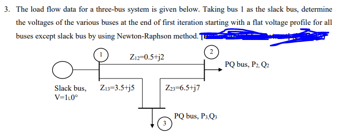
Trending now
This is a popular solution!
Step by step
Solved in 4 steps
- From, the given [Ybus] below, Find a). Eliminate firstly node 3 and then node 4 by using Kron Reduction method,calculate the new [Ybus]. b). Find the new [Z]. c). Find the equivalent circuit of the new 2-bus system.The figure below shows the one-line diagram of a simple three-bus power system withgeneration at bus 1. The voltage at bus 1 is V1 = 1.0∠0°per unit. The scheduledloads on buses 2 and 3 are marked on the diagram. Line impedances are marked inper unit on a 100 MVA base.(a) Using Gauss-Seidel method and initial estimates of ?2(0) = 1.0 + ?0, ?3(0) = 1.0 + ?0, determine V2and V3. Perform two iterations.(b) If after several iterations the bus voltages converge to?2 = 0.90 − ?0.10 pu?3 = 0.95 − ?0.05 pudetermine the line flows and line losses and the slack bus real and reactive power.In fast decoupled method of load flow study, the sparsity feature of Y bus minimizes the____________________________________________ requiremen
- For the system in Figure 4 with given generation and load dispatch determine the voltages after two itterations of Gauss-Seidel method. Assume the initial voltage to be 1.01 at angle of 0◦ pu at bus 1, 1.015 at angle of 0◦ pu at bus 2, and 1.0 at angle of 0◦ pu at bus 3. All line impedances are in per unit on a common base, and charging is neglected. Take base power of 100 MVA.1-Draw the structure of single bus bar system. 2-Write the methods of Neutral Grounding.Figure 5 shows a single-line diagram of a three-bus power system. Power flow input data are givenin Tables 1 and 2. (a) Determine the Ybus Matrix (b) Use Gauss-Seidel method to compute V2(1) and V3(1), the phase voltages at bus 2 and 3 after the first iteration. Use zero initial phase angles and 1.0 per-unit initial bus voltage magnitudes.
- What is the need to conduct power flow analysis? Discuss about data needed and bus types too.The 6-bus power system network of an electric utility company is shown in the Figure below. The line and transformer data containing the subtransient series resistance and reactance in per unit, and one-half of the total capacitance in per unit susceptance on a 100-MVA base, is tabulated below. The prefault voltage profile of the power system as obtained from four iterations of the newton Raphson power flow method are provided below as well.It is frequently more convenient to switch between auxiliary buses in parallel or employ a drop-and-pickup system. Why?