3. Write a reactance diagram for the network given Figure 1. G, T G: Inductance Load Station B Capacitance Load - Station C Station A Figure 1 Resistance Load
3. Write a reactance diagram for the network given Figure 1. G, T G: Inductance Load Station B Capacitance Load - Station C Station A Figure 1 Resistance Load

Chapter3: Magnetic Starters
Section: Chapter Questions
Problem 30SQ

Related questions
Question
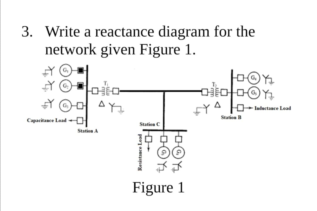
Transcribed Image Text:3. Write a reactance diagram for the
network given Figure 1.
G.
Inductance Load
Station B
Capacitance Load +
Station C
Station A
Figure 1
Resistance Load
Expert Solution
This question has been solved!
Explore an expertly crafted, step-by-step solution for a thorough understanding of key concepts.

Step by step
Solved in 2 steps with 2 images

Recommended textbooks for you

Delmar's Standard Textbook Of Electricity
Electrical Engineering
ISBN:
9781337900348
Author:
Stephen L. Herman
Publisher:
Cengage Learning

EBK ELECTRICAL WIRING RESIDENTIAL
Electrical Engineering
ISBN:
9781337516549
Author:
Simmons
Publisher:
CENGAGE LEARNING - CONSIGNMENT
Delmar's Standard Textbook Of Electricity
Electrical Engineering
ISBN:
9781337900348
Author:
Stephen L. Herman
Publisher:
Cengage Learning
EBK ELECTRICAL WIRING RESIDENTIAL
Electrical Engineering
ISBN:
9781337516549
Author:
Simmons
Publisher:
CENGAGE LEARNING - CONSIGNMENT

Electricity for Refrigeration, Heating, and Air C…
Mechanical Engineering
ISBN:
9781337399128
Author:
Russell E. Smith
Publisher:
Cengage Learning