35 mm 10 kN-m 2.36 x10° mm* G1 = 70 GPa (1) 40 mm C2 = (2) 4.02 x106 mm B 45 GPa 2800 mm 3600 mm A composite torsion member consists of two solid shafts joined at flange B. Shafts (1) and (2) are kN-m T1 attached to rigid supports at A and C, respectively. kN-m A concentrated torque T is applied to flange B in the direction shown. Determine the internal torques and shear stresses in each shaft. Also, determine the rotation angle of flange B. T2 MPa MPa ((Use the sign convention detailed in the fourth rad scene of this movie for internal torques and rotation angles.) PB I| || || I| |||| Shaft properties
35 mm 10 kN-m 2.36 x10° mm* G1 = 70 GPa (1) 40 mm C2 = (2) 4.02 x106 mm B 45 GPa 2800 mm 3600 mm A composite torsion member consists of two solid shafts joined at flange B. Shafts (1) and (2) are kN-m T1 attached to rigid supports at A and C, respectively. kN-m A concentrated torque T is applied to flange B in the direction shown. Determine the internal torques and shear stresses in each shaft. Also, determine the rotation angle of flange B. T2 MPa MPa ((Use the sign convention detailed in the fourth rad scene of this movie for internal torques and rotation angles.) PB I| || || I| |||| Shaft properties

Mechanics of Materials (MindTap Course List)
9th Edition
ISBN:9781337093347
Author:Barry J. Goodno, James M. Gere
Publisher:Barry J. Goodno, James M. Gere
Chapter11: Columns
Section: Chapter Questions
Problem 11.2.11P: The figure shows an idealized structure consisting of an L-shaped rigid bar structure supported by...

Related questions

Question
Transcribed Image Text:35 mm
10 kN-m
2.36 x106 mm
70 GPa
%3D
%3D
(1)
C2
40 mm
(2)
4.02 x106 mm
%3D
B
2800 mm
45 GPa
C
3600 mm
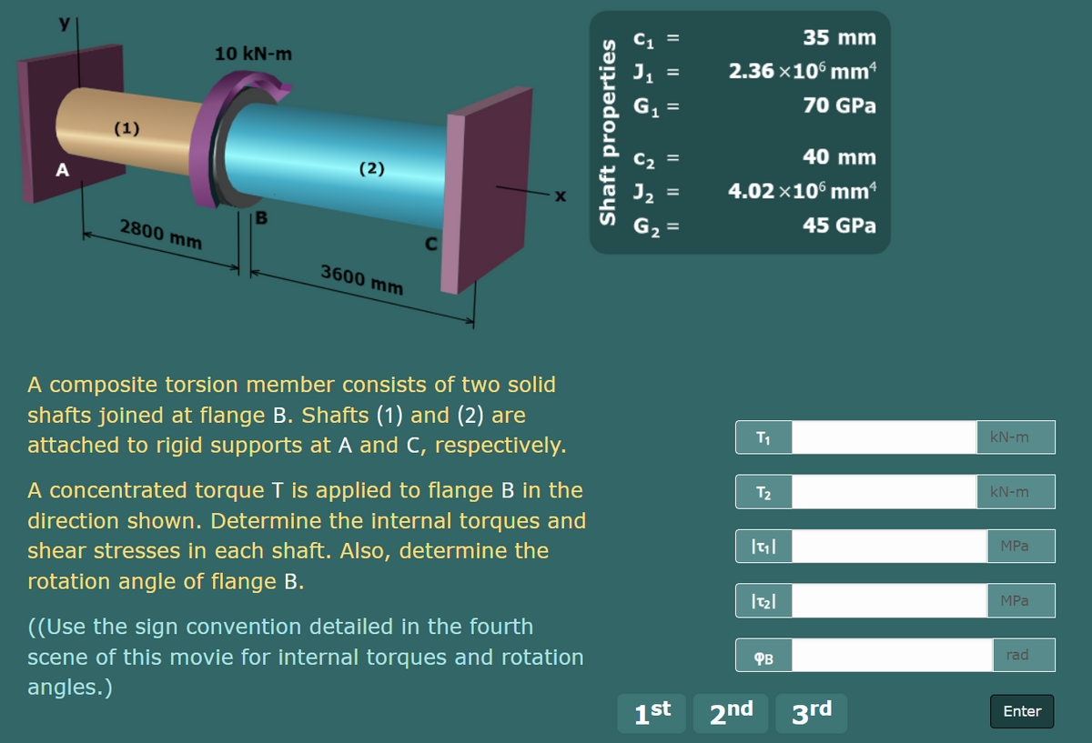
A composite torsion member consists of two solid
shafts joined at flange B. Shafts (1) and (2) are
attached to rigid supports at A and C, respectively.
T1
kN-m
A concentrated torque T is applied to flange B in the
T2
kN-m
direction shown. Determine the internal torques and
MPа
shear stresses in each shaft. Also, determine the
rotation angle of flange B.
MPa
((Use the sign convention detailed in the fourth
scene of this movie for internal torques and rotation
angles.)
PB
rad
1st
2nd
3rd
Enter
Shaft properties
I| ||||
Expert Solution
This question has been solved!
Explore an expertly crafted, step-by-step solution for a thorough understanding of key concepts.

Step by step
Solved in 2 steps with 2 images

Knowledge Booster


Learn more about
Need a deep-dive on the concept behind this application? Look no further. Learn more about this topic, mechanical-engineering and related others by exploring similar questions and additional content below.Recommended textbooks for you
Mechanics of Materials (MindTap Course List)
Mechanical Engineering
ISBN:
9781337093347
Author:
Barry J. Goodno, James M. Gere
Publisher:
Cengage Learning
Mechanics of Materials (MindTap Course List)
Mechanical Engineering
ISBN:
9781337093347
Author:
Barry J. Goodno, James M. Gere
Publisher:
Cengage Learning