360X79 wide-flange section and is such that ced load P = 10 kN and to the couple moment at is the bending moment just to the right of
360X79 wide-flange section and is such that ced load P = 10 kN and to the couple moment at is the bending moment just to the right of

Mechanics of Materials (MindTap Course List)
9th Edition
ISBN:9781337093347
Author:Barry J. Goodno, James M. Gere
Publisher:Barry J. Goodno, James M. Gere
Chapter10: Statically Indeterminate Beams
Section: Chapter Questions
Problem 10.4.23P: A cant i levé r b ea m i s supported by a tie rod at B as shown. Both the tie rod and the beam are...

Related questions

Question
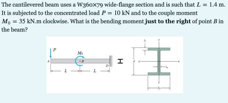
Transcribed Image Text:The cantilevered beam uses a W360x79 wide-flange section and is such that L = 1.4 m.
It is subjected to the concentrated load P = 10 kN and to the couple moment
Mo = 35 kN.m clockwise. What is the bending moment just to the right of point B in
the beam?
I
Mo
L
H
Expert Solution
This question has been solved!
Explore an expertly crafted, step-by-step solution for a thorough understanding of key concepts.

Step by step
Solved in 3 steps with 1 images

Knowledge Booster


Learn more about
Need a deep-dive on the concept behind this application? Look no further. Learn more about this topic, mechanical-engineering and related others by exploring similar questions and additional content below.Recommended textbooks for you
Mechanics of Materials (MindTap Course List)
Mechanical Engineering
ISBN:
9781337093347
Author:
Barry J. Goodno, James M. Gere
Publisher:
Cengage Learning
Mechanics of Materials (MindTap Course List)
Mechanical Engineering
ISBN:
9781337093347
Author:
Barry J. Goodno, James M. Gere
Publisher:
Cengage Learning