4/ For the figure below the spring is used to stop a 10 package. If the maximum deflection in the spring is 70 m, (a) the total work of the system in the figure below
4/ For the figure below the spring is used to stop a 10 package. If the maximum deflection in the spring is 70 m, (a) the total work of the system in the figure below

Mechanics of Materials (MindTap Course List)
9th Edition
ISBN:9781337093347
Author:Barry J. Goodno, James M. Gere
Publisher:Barry J. Goodno, James M. Gere
Chapter9: Deflections Of Beams
Section: Chapter Questions
Problem 9.4.4P: -4 A beam with a uniform load has a sliding support at one end and spring support at the other. The...

Related questions
Question
Please I need solve this in quickly time please
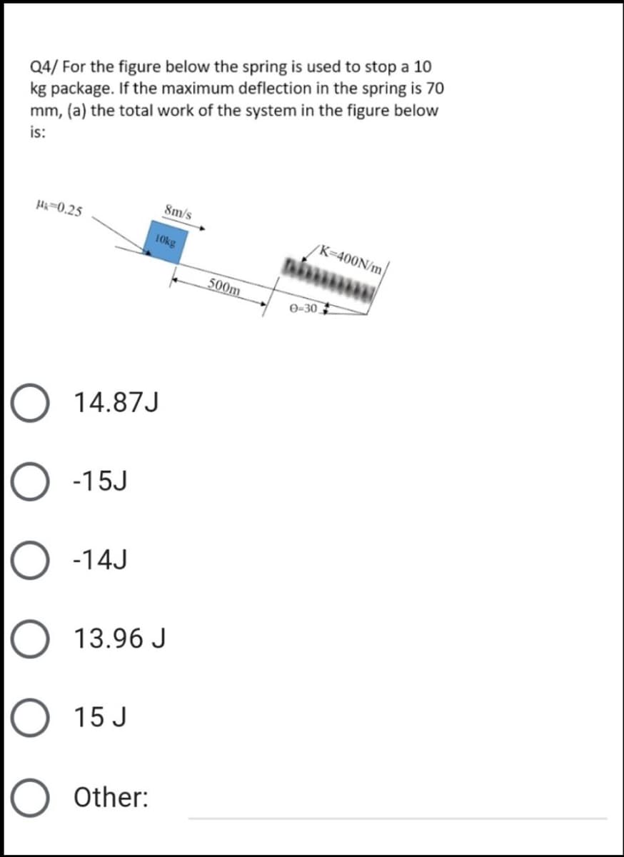
Transcribed Image Text:Q4/ For the figure below the spring is used to stop a 10
kg package. If the maximum deflection in the spring is 70
mm, (a) the total work of the system in the figure below
is:
8m/s
H=0.25
/K=400N/m
10kg
500m
0-30
14.87J
-15J
-14J
13.96 J
15 J
Other:
Transcribed Image Text:(b): The total work when
theta =0 equal to:
O 14.259
O -14.959 J
O -14 J
O -13.85J
O 13.32J
Other:
O O O O
Expert Solution
This question has been solved!
Explore an expertly crafted, step-by-step solution for a thorough understanding of key concepts.

Step by step
Solved in 2 steps with 2 images

Knowledge Booster


Learn more about
Need a deep-dive on the concept behind this application? Look no further. Learn more about this topic, mechanical-engineering and related others by exploring similar questions and additional content below.Recommended textbooks for you
Mechanics of Materials (MindTap Course List)
Mechanical Engineering
ISBN:
9781337093347
Author:
Barry J. Goodno, James M. Gere
Publisher:
Cengage Learning
Mechanics of Materials (MindTap Course List)
Mechanical Engineering
ISBN:
9781337093347
Author:
Barry J. Goodno, James M. Gere
Publisher:
Cengage Learning