4. A combinational logic circuit that compares between two 2-bit numbers A (AI A0) and B (RI RO) is designed. Output Fis high when A > R and kow when A


Q: Design a logic circuit with four inputs and one output that will produce "1" in the output only if…
A:
Q: Q3Given a Boolean expression F=AB+ABC+ABC+ABC a. Draw logic circuit for this expression b. By…
A:
Q: A Boolean expression is given as follow: F = (A+ B)C+ D)B (i) Draw a logic gate circuit to represent…
A:
Q: 2. The Boolean Algebra expression is given as Q = A(BC + BC + BC) + ABC %3D a. Convert this logical…
A: giVen Q=A'(B'C+BC+BC')+ABC
Q: Design a combinational Logic circuit in which whenever input is an even number between 1 and 10 a…
A: The logic circuit can be designed by using the truth table and the reduced Boolean expression can be…
Q: For the logic equation Q = AB+ CD’ , to make the output 1, which values of the inputs A, B, C, D…
A:
Q: ) Logic Function F (x, y, z, w) = ∑ m (0,2,4,6,10,13) + ∑ k (8,12) as sum of minimers is given a)…
A:
Q: 22. A manufacturing process is controlled by a built in logic circuit which is made up of AND, OR…
A:
Q: 1. Given the Boolean expression (b + d)(a’+ b’ + c), a. Convert the expression to the other standard…
A: We are authorized to answer three subparts at a time, since you have not mentioned which part you…
Q: Simplify the following Boolean function F, together with don’t care conditions d, and then express…
A: Simplify the following Boolean function F, don’t care conditions d, the express the simplified…
Q: Analyse, optimise and enhance a sequential logic circuit, making use of Timing Diagrams pls…
A: Sequential logic circuit- It is a circuit whose output is depend on the present input value as well…
Q: A B D
A: Given: The logic circuit is
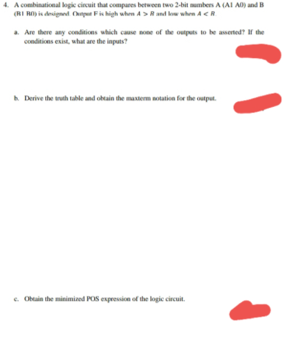
Q: 4. A combinational logic circuit that compares between two 2-bit numbers A (AI A0) and B (B1 B0) is…
A: The digital circuits can be combinational circuits as well as sequential circuits. The combinational…
Q: Q1. Determine the output waveform and Boolean expression X of the logic circuit in given circuit.
A: Given circuit Y1 is the output of bubbled OR gate Y1=A'+B' Y3 is the output of NAND gate Whose…
Q: Simplify the following boolean function by using a four variable K-map: f(w,x.y,z)-wx+xy'z Draw the…
A: Logic gates: Logic gates are the building blocks of any digital system. These circuits having one or…
Q: b) Develop the truth table for the combinational logic circuit shown below.
A: Given combinational logic circuit shown
Q: Determine the simplified Sum-of-Product (SOP) and Product-of-Sum (POS) expression for the given…
A: In this question we simplified the given Boolean expression with the help of k map in SOP and POS…
Q: Minimize the following Boolean function use five variables K-map 1. In SOP and draw the logic…
A:
Q: 1. A combinational circuit with two inputs X, Y and Z, and three outputs, A, B and C. when the…
A: The truth table can be obtained by considering the given condition for designing the digital…
Q: Design a combinational circuit that adds one to a 4-bit binary number. For example, if the input of…
A: Design a combinational circuit that adds one to a 4-bit binary number. For example, if the input of…
Q: Given a sequential logic circuit expression as X(t+1) = p'X+pY Y(t+1) = pX'+p'Y where X and Y are…
A: Consider the given sequential logic circuit expression, Xt+1=p'X+pYYt+1=pX'+p'Y To make the circuit,…
Q: Q2 Determine the Boolean expression for the logic circuit shown in Figure below. Simplify the…
A:
Q: We need a logic circuit that gives an output X that is high only if a given hexadecimal digit is…
A:
Q: Design a combinational circuit that accepts a 2-bit number (AB) and generates a 5-bit binary number…
A:
Q: Write the Boolean expression from given logic circuit diagram and simplify the output. Please show…
A: The Boolean expression can be obtained by writing the expression across all the gates.
Q: Apply Boolean algebra to digital logic circuit analysis A BC DE FG 10 12 13 14 15
A:
Q: The function of a programming is given below: F = A'B'C'D + A'B'CD' + A'BC'D + A'BCD' + AB'C'D +…
A: (1): The given function is: F = A'B'C'D + A'B'CD' + A'BC'D + A'BCD' + AB'CD' + ABC'D + ABCD' The…
Q: Q2 Determine the Boolean expression for the logic circuit shown in Figure below. Simplify the…
A: The solution can be achieved as follows.
Q: The expression of a logic circuit whose output is X is given below. Find the simplified POS…
A:
Q: Q 1):Write down the boolean equation for the circuit diagram given below and obtain its truth table.…
A: To find the simplified output of the given circuit
Q: Smplify, then wirte truth table and draw logic circuit. F (A, B, С) %3D (АВӨВС) + (А + ВC)
A:
Q: a. Construct a Karnaugh map for the logic function F = A ¯ B C ¯ D ¯ +AB C ¯ D ¯ + A ¯ B C ¯ D +AB C…
A: The above function is given as K-map is given as
Q: Draw the Logic circuit for the Boolean expression given below. Y= (A + B) (B.C) O ( C.D) %3D
A:
Q: For Q(a,b,c)= ∏M(0,2,4,6) what is the reduced form of the logic function in POS form?
A:
Q: A car seat belt interlock requires that the car should only start if the driver's seat belt is…
A: By considering the given condition, first, we can form a truth table and then the boolean expression…
Q: Q2 Determine the Boolean expression for the logic circuit shown in Figure below. Simplify the…
A: To determine the Boolean expression for the given logic circuit And simplify the expression using…
Q: Design a logic circuit with four inputs and one output that will produce "1" in the output only if…
A:
Q: 2. Design a combinational logic circuit for 4-input majority circuit. A majority circuit is one…
A: A3 A2 A1 A0 Output 0 0 0 0 0 0 0 0 1 0 0 0 1 0 0 0 0 1 1 0 0 1 0 0 0 0 1 0 1 0 0 1 1 0…
Q: shows a BCD counter that produces a four-bit output representing the BCD code for the number of…
A: BCD - counter that counts from (0000)2 to (1001)2 a) xa = high when BCD counter value = 2,3 or 9 b)…
Q: Design a hazard-free combinational logic circuit to implement the following logic function: f(a, b,…
A: In a combinational circuit, because of the transition of one of the inputs, if the output…
Q: B/ Show the required steps to derive a Boolean expression in a simplified SOP form for the output Z…
A: Given circuit consists of NOR, AND, Exclusive NOR gate. 1) The output of NOR gate is Y=A+B¯=A¯.B¯ 2)…
Q: Using a 4-bit signed input P=P3P2P1P0 and a control input Z, use a 4-bit adder and any logic gates…
A: According to the question, for a 4-bit signed input P=P3P2P1P0 and a control input Z, we need to…
Q: Simplify the following Boolean function F(A,B,C,D) E(0,3,5,7,9,10,11,15) together with the…
A: Given Boolean function, FA,B,C,D=∑0,3,5,7,9,10,11,15dA,B,C,D=∑1,2,6,8,13
Q: For the logic diagram provided, give the logic expression for the output F. 35ns 25ns 5ns 25ns F-(…
A: Given the circuit diagram: We need to find the logic expression for the output F.
Q: Simplify the following Boolean function F, together with don't care, using K-maps and design the…
A: As per Bartleby guidelines we are allowed to solve only one question, please ask the rest again.
Q: B/ Show the required steps to derive a Boolean expression in a simplified SOP fom for the output Z…
A: Given circuit
Q: Simplify the following Boolean Expression and Implement the simplified Logic diagram with Truth…
A: Simplifying the diagram,we get,
Q: Consider the following logic function F (A, B, C, D) = E m (0, 2, 5, 6, 7, 8, 9, 12, 13, 15) a) Find…
A: It is given that: FA,B,C,D=∑m0,2,5,6,7,8,9,12,13,15

Step by step
Solved in 2 steps with 2 images


- A combinational logic circuit that compares between two 2-bit numbers A (A1 A0) and B(B1 B0) is designed. Output F is high when ? > ? and low when ? < ?. 1) Are there any undefined outputs? If there are any undefined outputs what are the inputs?Design a 4-bit arithmetic circuit, with two selection variables S1 and S0, that generates the arithmetic operations in the following table. Draw the logic diagram for a single bit stage. Note that B’ represents “Not B”. Draw the logic diagram for a single bit stag1-Using the Karnaugh Method, design and draw the circuit of the logic circuit that gives the result of the multiplication of the two-bit numbers "AB" and "CD" according to minterms (SOP). Do not make any further simplifications before or after the Karnaugh Method. In tables and Karnaugh, ensure that the least significant bit is on the far right and the entries are sorted alphabetically. Make sure that the circuit you have drawn is understandable, the function you have written and the truth table are readable.
- 8) Draw a logic circuit to implement the Boolean function F and with only NOR gates (AC+AB+BC)A combinational logic circuit with 4 bits Binary Coded Decimal (BCD) as inputs and 1-bit output having following conditions: • if the equivalent decimal number of the BCD is odd then output is 0 • if the equivalent decimal number of the BCD is even then output is 1 1- Draw the truth table. 2- Find the simplified logic function using K-Map.Simplify the following function and draw a logic circuit using,
- Which of the following statements accurately represents the best method of logic circuit simplification? a. Actual circuit trial and error evaluation and waveform analysis b. Boolean algebra and actual circuit trial and error evaluation c. Karnaugh mapping and circuit waveform analysis d. Karnaugh mapping and Boolean algebraCreate a logic diagram out of this boolean expression. CD+BD+BC+AD+AC+AB Note: All inputs A B C and D must be together.You want to design an arithmetic comparison combined logic circuit. (a) List the steps that you will apply in the design approach. Design a 4-bit comparison (large-equal-small) circuit. Explain each step. With AND, OR, NOT gatesmake it happen. (b)By comparing the numbers 9 and 1 in the circuit you designed, the resultdiscuss.
- .Provide a detailed report on the combinational logic circuits below. 1. Magnitude Comparators a. What are magnitude comparators? b. How does it work? c. Applications of magnitude comparators.a) Design a logic circuit with three inputs A, B, C and an output that goes LOW only when A is HIGH while B and C are different. Draw and upload the circuit if you can, or at least describe it in words. b) Which logic gates produce a 1 output in the disabled state? c) Which logic gates pass the inverse of the input signal when these gates are enabled? d) What is the normal resting state of the SET’ and RESET’ inputs of a latch circuit (the prime is same as bar)? What is the active state of each input? e) What is the normal resting state of the NOR latch inputs? What is the active state?A circuit which takes a binary-coded decimal (BCD) number as input s to be designed such that the single output Q is true if the input is a prime number (remerber that 0 and 1 count as prime numbers). (a)Draw a truth table that specifies the above circuit (b)Using the truth table you have constructed and the Karnaugh map method find the minimised Boolean expression for the output Q. (c)Implement the digital circuit using the minimum number of 2-input logic AND, OR gates and inverters (NOT.