7.48 The transistor amplifier in Fig. P7.48 is biased with a current source I and has a very high B. Find the de voltage at the collector, Ve. Also, find the value of r̟. Replace the transistor with the T model of Fig. 7.26(b) (note that the de current source I should be replaced with an open circuit). Hence find the voltage gain v,/v,. +3 V F 7. 10 ΚΩ o Vc + Uc Si ca ar re tr. DI = 0.2 mA Figure P7.48
7.48 The transistor amplifier in Fig. P7.48 is biased with a current source I and has a very high B. Find the de voltage at the collector, Ve. Also, find the value of r̟. Replace the transistor with the T model of Fig. 7.26(b) (note that the de current source I should be replaced with an open circuit). Hence find the voltage gain v,/v,. +3 V F 7. 10 ΚΩ o Vc + Uc Si ca ar re tr. DI = 0.2 mA Figure P7.48

Delmar's Standard Textbook Of Electricity
7th Edition
ISBN:9781337900348
Author:Stephen L. Herman
Publisher:Stephen L. Herman
Chapter29: Dc Generators
Section: Chapter Questions
Problem 16RQ: Explain the difference between cumulative- and differential-compounded connections.

Related questions
Question
100%
Hi, I need the answer for question 7.48
Your kind help would be appreciated
Transcribed Image Text:Microelectronic_Circuits_by_Sedra_Smith.pdf - Foxit Reader
O
File
Home
Comment
Fill & Sign
View
Form
Protect
Share
Connect
Help
O Tell me what you want to do...
7.15
O SnapShot
6 Clipboard -
O 150%
O Fit Page
T
D Fit Width
A Link
A Bookmark
U File Attachment
TI
Rotate Left
Image Annotation
Hand Select
Actual
Reflow
Typewriter Highlight
D Fit Visible
Rotate Right
O Audio & Video
Size
Tools
View
Comment
Links
Insert
福听PDF转Word
Start
Microelectronic_Circuits_...
7.47 Show that the T model of Fig. 7.26(b) is the incremental
T'sig
version of the large-signal model of Fig. 6.5(b).
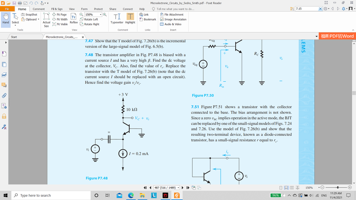
7.48 The transistor amplifier in Fig. P7.48 is biased with a
+
Rc
current source I and has a very high B. Find the de voltage
Vsig
at the collector, Vc. Also, find the value of r.. Replace the
transistor with the T model of Fig. 7.26(b) (note that the de
current source I should be replaced with an open circuit).
Hence find the voltage gain v/v;.
Rin
+3 V
Figure P7.50
7.51 Figure P7.51 shows a transistor with the collector
10 kM
connected to the base. The bias arrangement is not shown.
Since a zero vBC implies operation in the active mode, the BJT
can be replaced by one of the small-signal models of Figs. 7.24
and 7.26. Use the model of Fig. 7.26(b) and show that the
o Vc + vc
resulting two-terminal device, known as a diode-connected
transistor, has a small-signal resistance r equal to r,.
Vj
V)I = 0.2 mA
Figure P7.48
11 487 (516 / 1489)
150%
11:29 AM
O Type here to search
日
96%
1 4») G ENG
11/4/2021
LEMS
Transcribed Image Text:Microelectronic_Circuits_by_Sedra_Smith.pdf - Foxit Reader
O
File
Home
Comment
Fill & Sign
View
Form
Protect
Share
Connect
Нер
O Tell me what you want to do...
7.26(b)
O SnapShot
B Clipboard -
A Link
Ô Fit Page
T
D Fit Width
e 150%
O File Attachment
TI
Rotate Left
A Bookmark
e Image Annotation
Hand Select
Actual
Reflow
Typewriter Highlight
D Fit Visible
Rotate Right
O Audio & Video
Size
Tools
View
Comment
Links
Insert
福听PDF转Word
Start
Microelectronic_Circuits_...
7.2 Small-Signal Operation and Models 409
C
ic
ai,
8m Vbe
8m =
IÇNT
VT
re =
IE
Bo
Во
&m
Vbe
re
he
E
E
(а)
(b)
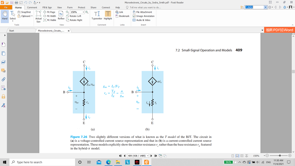
Figure 7.26 Two slightly different versions of what is known as the T model of the BJT. The circuit in
(a) is a voltage-controlled current source representation and that in (b) is a current-controlled current source
representation. These models explicitly show the emitter resistance r rather than the base resistance r_ featured
in the hybrid-n model.
11 409 (438 / 1489)
目昌目非
150%
11:30 AM
O Type here to search
日
96%
1 4) G ENG
11/4/2021
Expert Solution
This question has been solved!
Explore an expertly crafted, step-by-step solution for a thorough understanding of key concepts.

This is a popular solution!

Trending now
This is a popular solution!

Step by step
Solved in 2 steps with 2 images

Knowledge Booster


Learn more about
Need a deep-dive on the concept behind this application? Look no further. Learn more about this topic, electrical-engineering and related others by exploring similar questions and additional content below.Recommended textbooks for you
Delmar's Standard Textbook Of Electricity
Electrical Engineering
ISBN:
9781337900348
Author:
Stephen L. Herman
Publisher:
Cengage Learning
Delmar's Standard Textbook Of Electricity
Electrical Engineering
ISBN:
9781337900348
Author:
Stephen L. Herman
Publisher:
Cengage Learning