8-48 A beam is loaded and supported as shown in Fig. Using the coordinate axes shown, write equations tor the shear V and bending moment M for any section of the beam In the interval 2 m
8-48 A beam is loaded and supported as shown in Fig. Using the coordinate axes shown, write equations tor the shear V and bending moment M for any section of the beam In the interval 2 m

Mechanics of Materials (MindTap Course List)
9th Edition
ISBN:9781337093347
Author:Barry J. Goodno, James M. Gere
Publisher:Barry J. Goodno, James M. Gere
Chapter5: Stresses In Beams (basic Topics)
Section: Chapter Questions
Problem 5.6.18P: A beam having a cross section in the form of a channel (sec figure) is subjected to a bending moment...

Related questions
Question
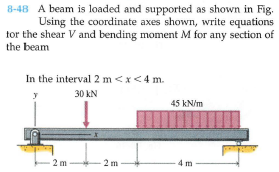
Transcribed Image Text:8-48 A beam is loaded and supported as shown in Fig.
Using the coordinate axes shown, write equations
tor the shear V and bending moment M for any section of
the beam
In the interval 2 m<x<4 m.
30 kN
45 kN/m
2 m
2 m
4 m
Expert Solution
This question has been solved!
Explore an expertly crafted, step-by-step solution for a thorough understanding of key concepts.

This is a popular solution!

Trending now
This is a popular solution!

Step by step
Solved in 3 steps with 5 images

Recommended textbooks for you
Mechanics of Materials (MindTap Course List)
Mechanical Engineering
ISBN:
9781337093347
Author:
Barry J. Goodno, James M. Gere
Publisher:
Cengage Learning
Mechanics of Materials (MindTap Course List)
Mechanical Engineering
ISBN:
9781337093347
Author:
Barry J. Goodno, James M. Gere
Publisher:
Cengage Learning