A 2082V, 1500-kVA 0.8-PF-lagging 60-Hz two-pole Y-connected synchronous generator has a synchronous reactance of 1.5 Ω and an armature resistance of 0.25 Ω. At 60 Hz, its friction and windage losses are 24 kW, and its core losses are 18 kW. The field circuit has a dc voltage of 200 V, and the maximum is 10 A. The resistance of the field circuit is adjustable over the range from 20 to 200 Ω. The OCC of this generator is shown in Figure-1 Assume that the field current of the generator has been adjusted to a value of 5 A. Compute the terminal voltage of this generator be if it is connected to a ∆-connected load with an impedance of 20∠30° Ω ? Sketch the phasor diagram of this generator. Compute is the efficiency of the generator at these conditions? Now assume that another identical ∆-connected load is to be paralleled with the first one. What happens to the phasor diagram for the generator? What is the new terminal voltage after the load has been added? What must be done to restore the terminal voltage to its original value?
A 2082V, 1500-kVA 0.8-PF-lagging 60-Hz two-pole Y-connected synchronous generator has a synchronous reactance of 1.5 Ω and an armature resistance of 0.25 Ω. At 60 Hz, its friction and windage losses are 24 kW, and its core losses are 18 kW. The field circuit has a dc voltage of 200 V, and the maximum is 10 A. The resistance of the field circuit is adjustable over the range from 20 to 200 Ω. The OCC of this generator is shown in Figure-1 Assume that the field current of the generator has been adjusted to a value of 5 A. Compute the terminal voltage of this generator be if it is connected to a ∆-connected load with an impedance of 20∠30° Ω ? Sketch the phasor diagram of this generator. Compute is the efficiency of the generator at these conditions? Now assume that another identical ∆-connected load is to be paralleled with the first one. What happens to the phasor diagram for the generator? What is the new terminal voltage after the load has been added? What must be done to restore the terminal voltage to its original value?

Introductory Circuit Analysis (13th Edition)
13th Edition
ISBN:9780133923605
Author:Robert L. Boylestad
Publisher:Robert L. Boylestad
Chapter1: Introduction
Section: Chapter Questions
Problem 1P: Visit your local library (at school or home) and describe the extent to which it provides literature...

Related questions

Question
100%
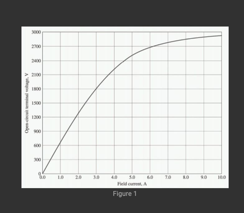
A 2082V, 1500-kVA 0.8-PF-lagging 60-Hz two-pole Y-connected synchronous generator has a synchronous reactance of 1.5 Ω and an armature resistance of 0.25 Ω. At 60 Hz, its friction and windage
losses are 24 kW, and its core losses are 18 kW. The field circuit has a dc voltage of 200 V, and the
maximum is 10 A. The resistance of the field circuit is adjustable over the range from 20 to 200 Ω.
The OCC of this generator is shown in Figure-1
Assume that the field current of the generator has been adjusted to a value of 5 A.
Compute the terminal voltage of this generator be if it is connected to a ∆-connected load with an impedance of 20∠30° Ω ?
Sketch the phasor diagram of this generator.
Compute is the efficiency of the generator at these conditions?
Now assume that another identical ∆-connected load is to be paralleled with the first one. What happens to the phasor diagram for the generator? What is the new terminal voltage after the load has been added?
What must be done to restore the terminal voltage to its original value?
Transcribed Image Text:3000
2700
2400
2100
1800
1500
1200
900
600
300
0.0
1.0
2.0
3.0
4.0
5.0
6.0
7.0
8.0
9.0
10.0
Field current, A
Figure 1
Open-circuit terminal voltage, V
Expert Solution
This question has been solved!
Explore an expertly crafted, step-by-step solution for a thorough understanding of key concepts.

This is a popular solution!

Trending now
This is a popular solution!

Step by step
Solved in 2 steps with 2 images

Knowledge Booster


Learn more about
Need a deep-dive on the concept behind this application? Look no further. Learn more about this topic, electrical-engineering and related others by exploring similar questions and additional content below.Recommended textbooks for you
Introductory Circuit Analysis (13th Edition)
Electrical Engineering
ISBN:
9780133923605
Author:
Robert L. Boylestad
Publisher:
PEARSON

Delmar's Standard Textbook Of Electricity
Electrical Engineering
ISBN:
9781337900348
Author:
Stephen L. Herman
Publisher:
Cengage Learning

Programmable Logic Controllers
Electrical Engineering
ISBN:
9780073373843
Author:
Frank D. Petruzella
Publisher:
McGraw-Hill Education
Introductory Circuit Analysis (13th Edition)
Electrical Engineering
ISBN:
9780133923605
Author:
Robert L. Boylestad
Publisher:
PEARSON
Delmar's Standard Textbook Of Electricity
Electrical Engineering
ISBN:
9781337900348
Author:
Stephen L. Herman
Publisher:
Cengage Learning
Programmable Logic Controllers
Electrical Engineering
ISBN:
9780073373843
Author:
Frank D. Petruzella
Publisher:
McGraw-Hill Education

Fundamentals of Electric Circuits
Electrical Engineering
ISBN:
9780078028229
Author:
Charles K Alexander, Matthew Sadiku
Publisher:
McGraw-Hill Education

Electric Circuits. (11th Edition)
Electrical Engineering
ISBN:
9780134746968
Author:
James W. Nilsson, Susan Riedel
Publisher:
PEARSON

Engineering Electromagnetics
Electrical Engineering
ISBN:
9780078028151
Author:
Hayt, William H. (william Hart), Jr, BUCK, John A.
Publisher:
Mcgraw-hill Education,