A 3 phase, 50 Hz, 434-V, supply is connected to a, Y-connected induction motor and synchronous motor. Impedance of each phase of induction motor is (1.25 +j2.17). The 3-phase synchronous motor draws a current of 120 A at 0.87 leading p.f. Two-wattmeter method is used to measure the total power. If the phase sequence is positive. Calculate a) reading on each wattmeter b) combined power factor.
A 3 phase, 50 Hz, 434-V, supply is connected to a, Y-connected induction motor and synchronous motor. Impedance of each phase of induction motor is (1.25 +j2.17). The 3-phase synchronous motor draws a current of 120 A at 0.87 leading p.f. Two-wattmeter method is used to measure the total power. If the phase sequence is positive. Calculate a) reading on each wattmeter b) combined power factor.

Power System Analysis and Design (MindTap Course List)
6th Edition
ISBN:9781305632134
Author:J. Duncan Glover, Thomas Overbye, Mulukutla S. Sarma
Publisher:J. Duncan Glover, Thomas Overbye, Mulukutla S. Sarma
Chapter3: Power Transformers
Section: Chapter Questions
Problem 3.25P: Consider a single-phase electric system shown in Figure 3.33. Transformers are rated as follows:...

Related questions

Question
pleasee provide me ur complete solution!
Transcribed Image Text:A 3 phase, 50 Hz, 434-V, supply is connected to a, Y-connected induction motor and synchronous
motor. Impedance of each phase of induction motor is (1.25 +j2.17) 2. The 3-phase synchronous
motor draws a current of 120 A at 0.87 leading p.f. Two-wattmeter method is used to measure the
total power. If the phase sequence is positive. Calculate a) reading on each wattmeter b) combined
power factor.
You can use the sample problem below as guide answering the problem, please use 3 decimal points
for the final answer!
Sample Problem solution for guide (the given from this problem is different from the problem above)
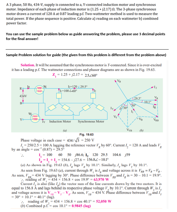
Solution. It will be assumed that the synchronous motor is Y-connected. Since it is over-excited
it has a leading p.f. The wattmeter connections and phasor diagrams are as shown in Fig. 19.63.
Z₁ = 1.25 +2.17 = 25/60°
12-120 /29.5°
voor
R$
1-1002-60°
434V
29.5°
B
ww
Yo-
Govor
ly Induction Motor
Synchronous Motor
VRB
VYB (b)
Fig. 19.63
Phase voltage in each case = 434/√3 = 250 V
1₁=250/2.5=100 A lagging the reference vector V by 60°. Current 1₂ = 120 A and leads V
by an angle = cos¹ (0.87) = 29.5°
1₁ = 100 60 50 86.6; 1₂ 120 29.5 104.6 j59
1-1, +1₂=154.6-27.6= 156.82-10.1°
(a) As shown in Fig. 19.63 (b), 1 lags V by 10.1°. Similarly, I, lags V, by 10.1⁰.
R
As seen from Fig. 19.63 (a), current through W, is I, and voltage across it is VRB = VR-VB-
As seen, VRB-434 V lagging by 30°. Phase difference between VR and I is = 30-10.1 = 19.9⁰.
.. reading of W, = 434 x 156.8 x cos 19.9° = 63,970 W
Current I, is also (like I) the vector sum of the line currents drawn by the two motors. It is
equal to 156.8 Á and lags behind its respective phase voltage V, by 10.1°. Current through W₂ is I,
and voltage across it is V,
V. As seen, Vy=434 V. Phase difference between V and
YB
ly
= 30° +10.1° = 40.1° (lag).
.. reading of W₂ = 434 x 156.8 x cos 40.1° = 52,050 W
(b) Combined p.f.= cos 10.1°= 0.9845 (lag)
W₂
www
10.1°
ܕܐ
IR
Expert Solution
This question has been solved!
Explore an expertly crafted, step-by-step solution for a thorough understanding of key concepts.

This is a popular solution!

Trending now
This is a popular solution!

Step by step
Solved in 2 steps with 1 images

Knowledge Booster


Learn more about
Need a deep-dive on the concept behind this application? Look no further. Learn more about this topic, electrical-engineering and related others by exploring similar questions and additional content below.Recommended textbooks for you
Power System Analysis and Design (MindTap Course …
Electrical Engineering
ISBN:
9781305632134
Author:
J. Duncan Glover, Thomas Overbye, Mulukutla S. Sarma
Publisher:
Cengage Learning
Power System Analysis and Design (MindTap Course …
Electrical Engineering
ISBN:
9781305632134
Author:
J. Duncan Glover, Thomas Overbye, Mulukutla S. Sarma
Publisher:
Cengage Learning