A balanced three-phase Y-connected power source is feeding three loads in parallel. Power source: 4160 V/835 kVA Load 1: 400 kW, p.f.=0.8, lagging Load 2: 150 kVA, p.f.=0.9, leading Load 3: 300 kW, p.f.=1 1) Is the power source able to feed the 3 loads simultaneously and why? 2) Give your design enabling the power source to feed the 3 loads simultaneously.
Q: 3. The load shown in Figure below consists of a resistance R in parallel with a capacitor of…
A: To solve above problem, one should have basic idea about working of AC circuits. Above given circuit…
Q: Zjine 1:10 10:1 Vg = 13.84 0° kV Zoad T T2 A 13.8-kV, single-phase generator supplies power to a…
A:
Q: Q1 (a) A 3 phase industrial load can be represented by a balanced star connected load (ZRN etc) of…
A: Given Three phase star connected industrial load of Zph=2G7+j6 ΩThe load is connected to source of…
Q: A balanced 3-phase load of 23.5 MVA with PF=0.85 lagging is supplied with a balanced 3-phase source…
A: The solution is given below
Q: Activity No. 2: Three loads are connected in parallel across a 1400 Vrms, 60 Hz single-phase supply…
A: I am attaching detailed solution image of this question.
Q: Example: A balanced positive-sequence wye-connected 60 Hz three-phase source has line-to- line…
A: The solution can be achieved as follows.
Q: A power system has 2 buses with bus1 as slack bus and bus 2 as PQ bus and bus voltages as V1=20 and…
A: we need to determine real and reactive power.
Q: The figure shows a single-phase power system with three loads. The source voltage is V = 240 20° V…
A: The detailed solution is provided below.
Q: Source: Ean = 12020° v; Epn = 1204 – 120° v; Een = 1204120° v (grounded neutral) Zan = Zpn = Zen =…
A: Given Condition : Without fault
Q: Q2) A single-phase equivalent circuit diagram of a balanced three-phase Y connected load that fed…
A: Given Z1=12+10j ΩZ2=8 KVARZ3=4.6ejπ7 KVAVs= 200ejπ6
Q: 2. Three parallel three-phase loads are supplied from a 207.85-Vrms, 60-Hz three-phase supply. The…
A: 1 Total kW=10+10=20 kW2 For reactive power=Active power of load 1=20 kWPower…
Q: jXL 1.cos(5t) a elll 土 V1 R1 -jXc Find the Thevenin equivalent of the above circuit and calculate…
A: Thevenin's Theorem: In a linear active bilateral network consisting no. of energy sources,…
Q: Q 2) The single-line diagram of a three-phase system is shown in Fig. 1. Using the common base Sp =…
A: Given data: Sb=50 MVAp.f=0.75
Q: PF improved by 100% Convert the given load of the circuit shown into impedance bulk by using power…
A: Given: Consider the following circuit: f=60 Hz To find: Convert the given load of the circuit shown…
Q: A) Three impedances Z1, Z2 and Z3 are delta-connected to a symmetrical 3-phase, 400 V supply of…
A:
Q: Q18. A 3-phase ring main ABCD fed at point A with 415V supplies balanced loads as shown in Figure…
A:
Q: Q1 (a) A 3 phase industrial load can be represented by a balanced star connected load (ZRN etc) of…
A:
Q: A factory takes a steady load of 0.22 MW at a 82% lagging (pf). The tariff is Rp 18000 per kVA of…
A: Given: A factory takes a steady load of 0.22 MW at an 82% lagging (pf). Peak load of factory, P=0.22…
Q: c) load Power Prafile cPr , Qt ,ST pfr). Aonder unbal anced Conaition without Faults a) load line…
A: We are given a network shown below: Given that: (1) Source voltages are:…
Q: Consider the circuit shown in Figure Q3. A delta- connected source supplies power to a delta-…
A: In this question, Find the load voltage at the load, currents in each phase, power dissipate in…
Q: The single-line diagram of a simple three-phase balanced power system with the components ratings is…
A: Given: The base voltage and base MVA are given at the load side as 500 MVA and 33 kV. We know that…
Q: v1 (V) VL (V)|11(A) | 12(A) IL (A) PI(W) | P2 (W) | Iin(A 429a.512 a577 bo 58 59.87 67 So o767 tit5…
A: “Since you have posted a question with multiple sub-parts, we will solve the first three sub-parts…
Q: Three-Phase Real Power. Assume the following three-phase voltages for a wye-connected balanced load…
A: Since you have posted a question with multiple sub-parts, we will solve first three sub-parts for…
Q: Question 1 Using Nodal Analysis, what is the value of Vg if the reference node is at node f if Z₁ =…
A:
Q: Figure Q2 below shows a manufacturing plant connected to three phase 3600 V line of wye…
A: Given data: The source is wye (star) connected and operating frequency is f=50 Hz. Sending end line…
Q: Q1) A single-phase equivalent circuit diagram of a balanced three-phase Y connected load that fed…
A: Single phase equivalent circuit are given as shown in the figured. Find the total complex power…
Q: Apply the delta-wye and wye-delta transformations in appropriate ac networks: For the circuit…
A: Given the circuit, as shown below: For the circuit below, Es = 24<30 V Z₁ = 2 + j2 ohms Z₂ = 4 -…
Q: Given the circuit fed by 50HZ voltage source Vs, knowing that Z, is an inductive load with 0.8 power…
A:
Q: Q3/ for the power system shown in figure. Find the optimal network condition of switches S1, S2 to…
A: To find optimum network condition for switches to get maximum steady state power transfer.The…
Q: A Y-connected balanced 3-phase source is supplying a balanced 3-phase load. The phase A voltage and…
A:
Q: Q4: A balanced three phase (Y-A) system, the delta load connected to a balanced three phase source…
A: In this question, 3 phase balance star connected sources to supply 3 phase balance Delta connected…
Q: The three-phase power and line-line ratings of the electric power system shown Figure-1 are given…
A: Given the three-phase power and line-line ratings of the electric power system, Let SAP ID = 8925…
Q: Given the circuit fed by 50HZ voltage source Vs, knowing that Z1 is an inductive load with 0.8 power…
A: Given circuit shown frequency f=50 HzZ1 is inductive load Z2 is capacitive load
Q: total apparent power supplied: 2400VA - power factor angle of the load: -25⁰ - line impedance:…
A:
Q: Q 2) The single-line diagram of a three-phase system is shown in Fig. 1. Using the common base Sp =…
A: The single - line diagram of a three - phase system is shown in figure (1). Using the common base…
Q: 2. For the 3-bus network shown in figure, the impedances indicated are in per unit. a) Draw pu…
A: given that - V1= 1∟0o V2=1.05∟90o (a) At node 1: I1 =Y1V1 + Y3 (V1-V3) + Y6 (V1 – V2) At node 2:…
Q: 12.6 Three balanced Y-connected loads are installed on a balanced three-phase four-wire system. Load…
A:
Q: Three impedances Z1, Z2 and Z3 are delta-connected to a symmetrical 3-phase, 400 V supply of phase…
A:
Q: Three loads are connected in parallel across a 1400 Vrms, 60 Hz single-phase supply a shown below. I…
A: active power P = apparent power S * power factor cos∅ reactive power Q = apparent power Q * sin∅ so…
Q: Course: Electrical Engineering Subject: Electrical Apparatus Instructions: Write the GIVEN with…
A:
Q: The three-phase balanced load system shown in the figure will be analyzed in a continuous sinusoidal…
A: consider the given question; vR (t) = Cost Volt, Z∆ = α + βj α=3, β=8
Q: Consider a portion of a power system with two generators (G1 and G2) in parallel connected to a…
A: The circuit diagram of the given problem is given as
Q: T1 T2 PROBLEM 4 Line + G M The three-phase power and line- line rating of the electric power system…
A:
Q: Q 2) The single-line diagram of a three-phase system is shown in Fig. 1. Using the common base Sp =…
A: Given base MUA=50MUA and Generator…
Q: A three-phase system has balanced conditions so that the per-phase circuit representation can be…
A: The three-phase system diagram is shown below, Here,The load voltage is,VL=4kVrmsThe load impedance…
Q: power
A: In this question, we have to answer about reactive power..
Q: The single line diagrams of interconnected power system show: Select one: a. All the network…
A: Choose the correct option The single line diagram of interconnected power system show?
Q: The single-line diagram of a simple three-phase balanced power system with the components ratings is…
A: We have authored only first part of the question due to its complexity. Please repost your question…
Q: Chapter 17: Problem 4 (Series-Parallel): For the network shown below, find: a) The total impedance…
A: As per the guidelines of Bartley we supposed to answer first three subpart only
Q: A balanced 3-phase load of 23.5 MVA with PF=0.85 lagging is supplied with a balanced 3-phase source…
A:
Please show all details. Thank you.
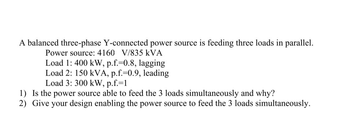
Trending now
This is a popular solution!
Step by step
Solved in 2 steps with 2 images
- Two balanced Y-connected loads, one drawing 10 kW at 0.8 power factor lagging and the other IS kW at 0.9 power factor leading, are connected in parallel and supplied by a balanced three-phase Y-connected, 480-V source. (a) Determine the source current. (b) If the load neutrals are connected to the source neutral by a zero-ohm neutral wire through an ammeter, what will the ammeter read?Two balanced Y-connected loads in parallel, one drawing 15 kW at 0.6 power factor lagging andthe other drawing 10 kVA at 0.8 power factor leading, are supplied by a balanced, three-phase,480-volt source.d. ∆-connected capacitors are now installed in parallel with the combined load. Whatvalue of capacitive reactance is needed in each leg of the ∆ to make the source powerfactor unity? Give your answer in W.e. Compute the magnitude of the current in each capacitor and the line current from thesourceI really need help understanding three phase systems. What can you tell me to make it more clear? When can a system be analyzed in its single-phase equivalent? Is it better/easier to have the load in the same configuration as the source? is power factor alwasy the cosing of the angle of the total impedance? Thank you
- The load impedance in the figure absorbs 2.5 kW and generates 5 kVAR The sinusoidal voltage source develops 7.5 kW. Suppose that R= 16.5Ω A)Find the min and max of the two inductive line reactances that will satisfy these constraints. B)For Xminobtained in part A,find the magnitudes of the total reactive power generated and the total reactive power absorbed in the circuit. C)For Xmax obtained in part A,find the magnitudes of the total reactive power generated and the total reactive power absorbed.1. Three impedances Z1, Z2 and Z3 are delta-connected to a symmetrical 3-phase, 400 V supply of phase sequence RYB. Z1 = (8 – j 6) Ω and is connected between lines R and Y. Z2 = (6 + j 8) Ω and is connected between lines Y and B. Z3 = (10 + j 0) Ω and is connected between lines B and R. Calculate (i) line and phase currents (ii) power per phase (iii) total power. Verify the results by creating a MATLAB Simulink model and program. Obtain the plots for the currents and voltages. Repeat for a case when the same loads are now connected in star.ABC phase sequential In a three-phase balanced Star-Star connected system, the phase on the source side voltage is 300 Vrms. The line impedance in the system is Zhat=1 ohm. star bound Each of the loads has a capacitive load of 5-j3 ohms and an inductive load of 9+j2 ohms. is the parallel connected form of the load. In the light of this information, a) Find the real power provided by the source. b) Determine the power factor of the source.
- S1) The serial impedance per unit length of a three-phase 140 km power transmission line is 0.09 + j0.88 ohm/ km and its admittance is j4.1x10-6 S / km. Power factor under 210 kV interphase voltage from the end of this energy transmission line A power of 150 MVA, which is 0.85 back, is drawn. Using this transmission line data and the T equivalent circuit model, the line Calculate the head voltage (V1), current (I1) and load angle.Consider the microgrid of Figure 3.66. A three-phase transformer, T1, israted at 500 kVA, 220 VY grounded/440 V delta, a transformerwith a reactance of 3.5%.Themicrogridis supplied from anAC bus of a PV generating station.The DC bus rated at 540 V.The distributionlineis 10mileslong and has a series impedance of 0.1 + j1.0 Ω per mile and local load of 100 kVA at 440 V. The microgrid is connected to the local power grid using a three-phase transformer T2, rated at 440 V Y grounded/13.2 kV delta,500 kVA with a reactance of 8%. Compute the per unitimpedance diagram of the microgrid system. Assume the voltage base of 13.2 kV on the local power grid side and kVA base of 500Apply the delta-wye and wye-delta transformations in appropriate ac networks: For the circuit below, Es = 24<30 V Z₁ = 2 + j2 ohms Z₂ = 4 - j3 ohms Z3 = 6 + j8 ohms Z4 = 8 - j6 ohms Z5 = 10 - j10 ohms Z6 = j12 ohms Calculate the complex power in Z4. PS: Show complete/step-by-step solution without rounding off any numbers
- A power system has 2 buses with bus1 as slack bus and bus 2 as PQ bus and bus voltages as V1=20 and V2=20. The admittances are Y11=Y22=492, Y12=Y21=181. Find the real and reactive power in the slack bus. Real Power = Reactive Power =element values are selected as R1 = 0.5Ω, R2 = 1Ω, J = 2A, E = 1V, β = 4 α = 1. 10Ω to A-B ends When the Ry load impedance is connected, the power consumed at this load is Norton for the circuit. Calculate using the equivalent.A three-phase system has balanced conditions so that the per-phase circuit representation can be used as shown in Figure 1 Select the turns ratio of the step-up and step-down transformers that the system operates with an efficiency greater than 99 percent. Moreover, find the complex power (received or given) of all components in the circuit and the V1 and V2 voltages. The load voltage is specified as 4 kV rms, and the load impedance is 4/3 ohm. ..