A bimetallic beam used in a temperature-control switch consists of strips of aluminum and coppe bonded together as shown in the figure, which is a cross-sectional view. The width of the beam i 1.0 in., and each strip has a thickness of 1/16 in. Under the action of a bending moment M =22.5 Ib-in. acting about the z axis, what are the maximum stresses oą and o, in the aluminum and copper, respectively? (Assume Ea = 10.5 x %3D 106 psi and E. = 16.8x 10⁶ psi .) %3D
A bimetallic beam used in a temperature-control switch consists of strips of aluminum and coppe bonded together as shown in the figure, which is a cross-sectional view. The width of the beam i 1.0 in., and each strip has a thickness of 1/16 in. Under the action of a bending moment M =22.5 Ib-in. acting about the z axis, what are the maximum stresses oą and o, in the aluminum and copper, respectively? (Assume Ea = 10.5 x %3D 106 psi and E. = 16.8x 10⁶ psi .) %3D

Mechanics of Materials (MindTap Course List)
9th Edition
ISBN:9781337093347
Author:Barry J. Goodno, James M. Gere
Publisher:Barry J. Goodno, James M. Gere
Chapter6: Stresses In Beams (advanced Topics)
Section: Chapter Questions
Problem 6.2.11P: A bimetallic beam used in a temperature-control switch consists of strips of aluminum and copper...

Related questions
Topic Video
Question
M=22.5 ib-in
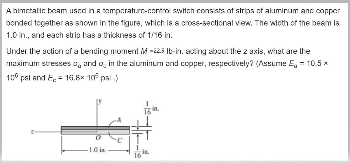
Transcribed Image Text:A bimetallic beam used in a temperature-control switch consists of strips of aluminum and copper
bonded together as shown in the figure, which is a cross-sectional view. The width of the beam is
1.0 in., and each strip has a thickness of 1/16 in.
Under the action of a bending moment M =22.5 |b-in. acting about the z axis, what are the
maximum stresses oą and o, in the aluminum and copper, respectively? (Assume Ea = 10.5 x
106 psi and E. = 16.8x 10⁶ psi .)
in.
16
1.0 in.
in.
16
Expert Solution
This question has been solved!
Explore an expertly crafted, step-by-step solution for a thorough understanding of key concepts.

This is a popular solution!

Trending now
This is a popular solution!

Step by step
Solved in 4 steps with 4 images

Knowledge Booster


Learn more about
Need a deep-dive on the concept behind this application? Look no further. Learn more about this topic, mechanical-engineering and related others by exploring similar questions and additional content below.Recommended textbooks for you
Mechanics of Materials (MindTap Course List)
Mechanical Engineering
ISBN:
9781337093347
Author:
Barry J. Goodno, James M. Gere
Publisher:
Cengage Learning
Mechanics of Materials (MindTap Course List)
Mechanical Engineering
ISBN:
9781337093347
Author:
Barry J. Goodno, James M. Gere
Publisher:
Cengage Learning