
Mechanics of Materials (MindTap Course List)
9th Edition
ISBN: 9781337093347
Author: Barry J. Goodno, James M. Gere
Publisher: Cengage Learning
expand_more
expand_more
format_list_bulleted
Videos
Textbook Question
Chapter 6, Problem 6.3.4P
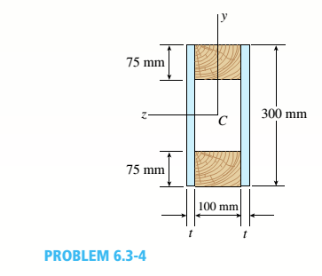
A simple beam of span length 3.2 m carries a uniform load of intensity 48 kN/m, The cross section of the beam is a hollow box with wood flanges and steel side plates, as shown in the figure. The wood flanges are 75 mm x 100 mm in cross section, and the steel plates are 300 mm deep.
What is the required thickness t of the steel plates if the allowable stresses are 120 M Pa for the steel and 6,5 M Pa for the wood? (Assume that the moduli of elasticity for the steel and wood are 210 GPa and 10 GPa, respectively, and disregard the weight of the beam.)
Expert Solution & Answer

Trending nowThis is a popular solution!

Chapter 6 Solutions
Mechanics of Materials (MindTap Course List)
Ch. 6 - A composite beam is constructed using a steel...Ch. 6 - A wood beam is strengthened using two steel plates...Ch. 6 - A composite beam consisting of fiberglass faces...Ch. 6 - A wood beam with cross-sectional dimensions 200 mm...Ch. 6 - A hollow box beam is constructed with webs of...Ch. 6 - A r o lukI f/frm f «m t ub e of ou t sid e d ia...Ch. 6 - A beam with a guided support and 10-ft span...Ch. 6 - A plastic-lined steel pipe has the cross-sectional...Ch. 6 - The cross section of a sand wie h beam consisting...Ch. 6 - The cross section of a sandwich beam consisting of...
Ch. 6 - A bimetallic beam used in a temperature-control...Ch. 6 - A simply supported composite beam 3 m long carries...Ch. 6 - A simply supported wooden I-beam with a 12-ft span...Ch. 6 - -14 A simply supported composite beam with a 3.6 m...Ch. 6 - -15 A composite beam is constructed froma wood...Ch. 6 - A wood beam in a historic theater is reinforced...Ch. 6 - Repeat Problem 6.2-1 but now assume that the steel...Ch. 6 - Repeat Problem 6.2-17 but now use a...Ch. 6 - A sandwich beam having steel faces enclosing a...Ch. 6 - A wood beam 8 in. wide and 12 in. deep (nominal...Ch. 6 - A simple beam of span length 3.2 m carries a...Ch. 6 - A simple beam that is 18 ft long supports a...Ch. 6 - The composite beam shown in the figure is simply...Ch. 6 - The cross section of a beam made of thin strips of...Ch. 6 - Consider the preceding problem if the beam has...Ch. 6 - A simple beam thai is IS ft long supports a...Ch. 6 - The cross section of a composite beam made of...Ch. 6 - A beam is constructed of two angle sections, each...Ch. 6 - The cross section of a bimetallic strip is shown...Ch. 6 - A W 12 x 50 steel wide-flange beam and a segment...Ch. 6 - A reinforced concrete beam (see figure) is acted...Ch. 6 - A reinforced concrete T-beam (see figure) is acted...Ch. 6 - A reinforced concrete slab (see figure) is...Ch. 6 - A wood beam reinforced using two channels is...Ch. 6 - A wood beam reinforced by an aluminum channel...Ch. 6 - A beam with a rectangular cross section supports...Ch. 6 - A wood beam with a rectangular cross section (see...Ch. 6 - Solve the preceding problem for the following...Ch. 6 - A simply supported wide-flange beam of span length...Ch. 6 - Solve the preceding problem using the fol...Ch. 6 - A wood cantilever beam with a rectangular cross...Ch. 6 - Solve the preceding problem for a cantilever beam...Ch. 6 - A 2-m-long cantilever beam is constructed using a...Ch. 6 - A wood beam AB with a rectangular cross section (4...Ch. 6 - A steel beam of I-section (see figure) is simply...Ch. 6 - A cantilever beam with a wide-flange cross section...Ch. 6 - Solve the preceding problem using a W 310 x 129...Ch. 6 - A cantilever beam of W 12 × 14 section and length...Ch. 6 - A cantilever beam built up from two channel...Ch. 6 - A built-Lip I-section steel beam with channels...Ch. 6 - Repeat Problem 6.4-14 but use the configuration of...Ch. 6 - A beam with a channel section is subjected to a...Ch. 6 - A beam with a channel section is subjected to a...Ch. 6 - An angle section with equal legs is subjected to a...Ch. 6 - An angle section with equal legs is subjected to a...Ch. 6 - A beam made up all woun equal leg angles is...Ch. 6 - The Z-section of Example D-7 is subjected to M = 5...Ch. 6 - The cross section of a steel beam is constructed...Ch. 6 - The cross section of a steel beam is shown in the...Ch. 6 - A beam with a semicircular cross section of radius...Ch. 6 - .10 A built-up bourn supporting a condominium...Ch. 6 - Asteelpost (E = 30 × 106 psi) having thickness t =...Ch. 6 - A C 200 x 17.1 channel section has an angle with...Ch. 6 - A cold-formed steel section is made by folding a...Ch. 6 - A simple beam with a W 10 x 30 wide-flange cross...Ch. 6 - Solve the preceding problem for a W 250 × 44.8...Ch. 6 - A beam of wide-flange shape, W 8 x 28, has the...Ch. 6 - Solve the preceding problem for a W 200 × 41,7...Ch. 6 - Calculate the distance e from the cent crime of...Ch. 6 - Calculate the distance e from the centerline of...Ch. 6 - The cross section of an unbalanced wide-flange...Ch. 6 - The cross section of an unbalanced wide-flange...Ch. 6 - The cross section of a channel beam with double...Ch. 6 - The cross section of a slit circular tube of...Ch. 6 - The cross section of a slit square tube of...Ch. 6 - The cross section of a slit rectangular tube of...Ch. 6 - A U-shaped cross section of constant thickness is...Ch. 6 - Derive the following formula for the distance e...Ch. 6 - Derive the following formula for the distance e...Ch. 6 - The cross section of a sign post of constant...Ch. 6 - A cross section in the shape of a circular arc of...Ch. 6 - Determine the shape factor f for a cross section...Ch. 6 - (a) Determine the shape factor/for a hollow...Ch. 6 - A propped cantilever beam of length L = 54 in....Ch. 6 - A steel beam of rectangular cross section is 40 mm...Ch. 6 - .5 Calculate the shape factor j for the...Ch. 6 - Solve the preceding problem for a wide-flange beam...Ch. 6 - Determine the plastic modulus Z and shape...Ch. 6 - Prob. 6.10.8PCh. 6 - Prob. 6.10.9PCh. 6 - Prob. 6.10.10PCh. 6 - A hollow box beam with height h = 16 in,, width h...Ch. 6 - Solve the preceding problem for a box beam with...Ch. 6 - A hollow box beam with height h = 9.5 in., inside...Ch. 6 - Solve the preceding problem for a box beam with...Ch. 6 - The hollow box beam shown in the figure is...Ch. 6 - Prob. 6.10.16PCh. 6 - Prob. 6.10.17PCh. 6 - A singly symmetric beam with a T-section (see...Ch. 6 - A wide-flange beam with an unbalanced cross...Ch. 6 - .20 Determine the plastic moment Mpfor beam having...
Knowledge Booster


Learn more about
Need a deep-dive on the concept behind this application? Look no further. Learn more about this topic, mechanical-engineering and related others by exploring similar questions and additional content below.Similar questions
- A steel beam of length L = 16 in. and cross-sectional dimensions h = 0.6 in. and h = 2 in. (see figure) supports a uniform load of intensity if = 240 lb/in., which includes the weight of the beam. Calculate the shear stresses in the beam (at the cross section of maximum shear force) at points located 1/4 in., 1/2 in., 3/4 in., and I in, from the top surface of the beam. From these calculations, plot a graph showing the distribution of shear stresses from top to bottom of the beam.arrow_forwardA W 310 x 52 steel beam is subjected to a point load P = 45 kN and a transverse load V = 20 kN at B. The beam has length L =2m.(a) Calculate the principal normal stresses and the maximum shear stress on element D located on the web right below the top flange and near the fixed support. Neglect the weight of the beam, (b) Repeat Part a atcentroid C (sec figure). See Table F-l(b), Appendix F, for beam propertiesarrow_forwardThe composite beam shown in the figure is simply supported and carries a total uniform load of 40 kN/m on a span length of 4.0 m. The beam is built of a southern pine wood member having cross-sectional dimensions of 150 mm × 250 mm and two brass plates of cross-sectional dimensions 30 mm × 150 mm. Determine the maximum stresses (7b and ctwin the brass and wood, respectively, if the moduli of elasticity are EB= % GPa and Ew= 14 GPa. (Disregard the weight of the beam.) Find the required thickness of the brass plates so that the plate and wood reach their allowable stress values of Eb= 70 MPa and t Ew= 8.5 MPa simultaneously under the maximum moment. What is the maximum moment?arrow_forward
- A square steel tube of a length L = 20 ft and width b2= 10.0 in. is hoisted by a crane (see figure). The lube hangs from a pin of diameter d that is held by the cables at points A and B. The cross section is a hollow square with an inner dimension b1= 8.5 in. and outer dimension b2= 10,0 in. The allowable shear stress in the pin is 8,700 psi. and the allowable bearing stress between the pin and the tube is 13,000 psi. Determine the minimum diameter of the pin in order to support the weight of the tube. Note: Disregard the rounded corners of the tube when calculating its weight.arrow_forwardA simple beam that is 18 ft long supports a uniform load of intensity q. The beam is constructed of two C8 x 11.5 sections (channel sections or C-shapes) on either side of a 4 × 8 (actual dimensions) wood beam (see the cross section shown in the figure part a). The modulus of elasticity of the steel (E; = 30,000 ksi) is 20 times that of the wood (Ew). (a) If the allowable stresses in the steel and wood are 12,000 psi and 900 psi, respectively, what is the allowable load qmax Note: Disregard the weight of the beam, and see Table F-3(a) of Appendix F for the dimensions and properties of the C-shape beam. (b) If the beam is rotated 90° to bend about its v axis (see figure part b) and uniform load q = 250 lb/ft is applied, find the maximum stresses trs and crw in the steel and wood, respectively Include the weight of the beam. (Assume weight densities of 35 lb/ft3 and 490 lb/ft3 for the wood and steel, respectively.)arrow_forwardA simple beam with a rectangular cross section (width, 3,5 inL; height, 12 in,) carries a trapczoi-dally distributed load of 1400 lb/ft at A and 1000 lb/ft at B on a span of 14 ft (sec figure). Find the principal stresses 2 and the maximum shear stress r__ at a cross section 2 ft from the left-hand support at each of the locations: (a) the neutral axis, (b) 2 in. above the neutral axis, and (c) the top of the beam. (Disregard the direct compressive stresses produced by the uniform load bearing against the top of the beam.)arrow_forward
- A cantilever beam(Z, = 6 ft) with a rectangular cross section (/> = 3.5 in., h = 12 in.) supports an upward load P = 35 kips at its free end. (a) Find the state of stress ((7T, o^., and r in ksi) on a plane-stress element at L/2 that is i/ = 8 in. up from the bottom of the beam. Find the principal normal stresses and maximum shear stress. Show these stresses on sketches of properly oriented elements. (b) Repeat part (a) if an axial compressive centroidal load N = 40 kips is added at Barrow_forwardA retaining wall 6 ft high is constructed of horizontal wood planks 2.5 in. thick (actual dimension) that are supported by vertical wood piles of a 12 in, diameter (actual dimension), as shown in the figure. The lateral earth pressure is pt=125 lb/ft2 at the top of the wall and p2= 425 lb/ft2 at the bottom. Assuming that the allowable stress in the wood is 1175 psi, calculate the maximum permissible spacing s of the piles. Find the required diameter of the wood piles so that piles and planks (f = 2.5 in.) reach the allowable stress at the same time. Hint: Observe that the spacing of the piles may be governed by the load-carrying capacity of either the planks or the piles. Consider the piles to act as cantilever beams subjected to a trapezoidal distribution of load, and consider the planks to act as simple beams between the piles. To be on the safe side, assume that the pressure on the bottom plank is uniform and equal to the maximum pressure.arrow_forwardA reinforced concrete slab (see figure) is reinforced with 13-mm bars spaced 160 mm apart at d = 105 mm from the top of the slab. The modulus of elasticity for the concrete is Ec= 25 GPa, while that of the steel is £s = 200 G Pa. Assume that allowable stresses for concrete and steel arecrac = 9.2 MPa and us = 135 MPa. l()5 mm Find the maximum permissible positive bending moment for a l-m wide strip of the slab. What is the required area of steel reinforcement, A^ if a balanced condition must be achieved? What is the allowable positive bending moment? (Recall that in a balanced design, both steel and concrete reach allowable stress values simultaneously under the design moment.)arrow_forward
- Beam ABC with an overhang BC is subjected to a linearly varying distributed load on span AB with peak: intensity q0= 2500 N/m and a point load P = 1250 N applied at C. The beam has a width ft = 100 mm and depth h = 200 mm. Find the state of plane stress at point D located 150 mm below the top of the beam and 0.2 m to the left of point B. Also find the principal stresses at D>Neglect the weight of the beam.arrow_forwardEach girder of the lift bridge (sec figure) is 180 ft long and simply supported at the ends. The design load for each girder is a uniform load of intensity 1,6 kips/ft. The girders are fabricated by welding three steel plates to form an I-shaped cross section (see figure) having section modulus S = 3600 in3. What is the maximum bending stress rmaxin a girder due to the uniform load?arrow_forwardA bimetallic beam used in a temperature-control switch consists of strips of aluminum and copper bonded together as shown in the figure, which is a cross-sectional view. The width of the beam is LO in,, and each strip has a thickness of 1/16 in. Under the action of a bending moment M = 12 lb-in, acting about the z axis, what are the maximum stresses aaand ecin the aluminum and copper, respectively? (Assume fA, = 10,5 x l0 psi and ecu= 16,8 × 10⁶ psi,)arrow_forward
arrow_back_ios
SEE MORE QUESTIONS
arrow_forward_ios
Recommended textbooks for you
 Mechanics of Materials (MindTap Course List)Mechanical EngineeringISBN:9781337093347Author:Barry J. Goodno, James M. GerePublisher:Cengage Learning
Mechanics of Materials (MindTap Course List)
Mechanical Engineering
ISBN:9781337093347
Author:Barry J. Goodno, James M. Gere
Publisher:Cengage Learning
Mechanics of Materials Lecture: Beam Design; Author: UWMC Engineering;https://www.youtube.com/watch?v=-wVs5pvQPm4;License: Standard Youtube License