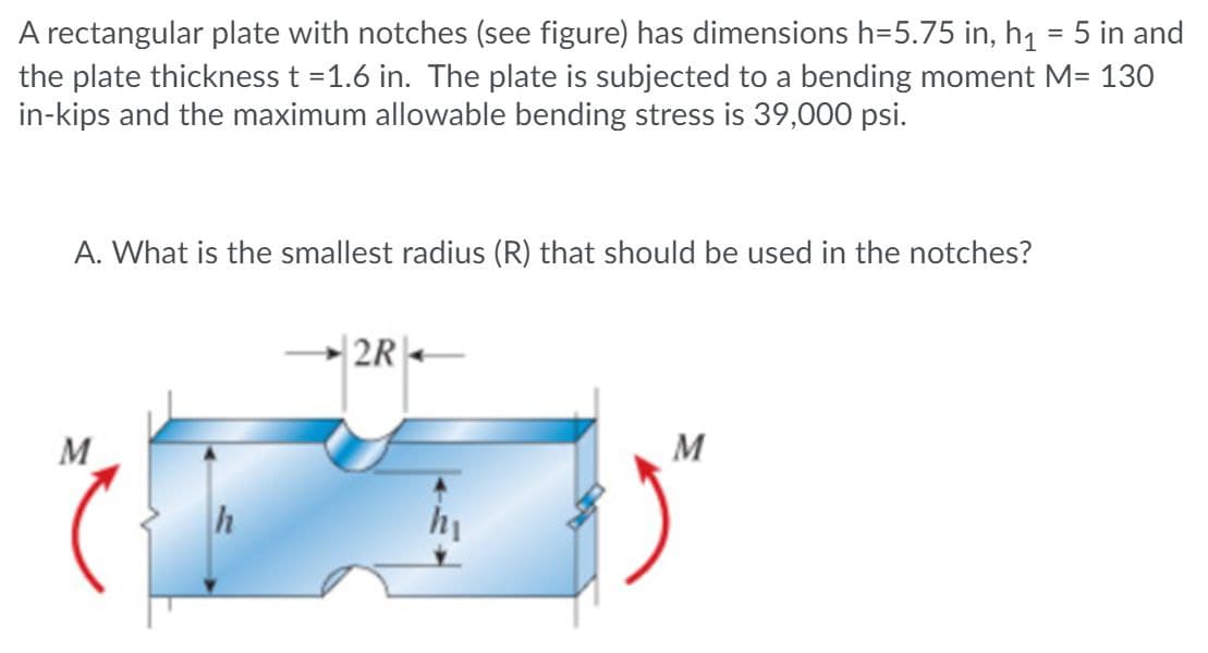
A rectangular plate with notches (see figure) has dimensions h=5.75 in, h1 = 5 in and the plate thickness t =1.6 in. The plate is subjected to a bending moment M= 130 in-kips and the maximum allowable bending stress is 39,000 psi. A. What is the smallest radius (R) that should be used in the notches? |2R M M


Q: H.W 3_ Two aluminum alloy plates (2) are attached to the sides of a wooden beam (1) as shown in…
A:
Q: A wood beam carries the loading shown in the figure calculate the magnitude of the bending stress…
A:
Q: For the loaded beam shown in Figure Q6 below, consider section M-M and detemine the following: 6.1…
A: Given Data: Length of the beam, L=0.4+0.3+0.4=1.1 m
Q: A simply supported beam AB = 9 m has a hollow rectangular cross-section with 18 cm as width, 23 cm…
A: According to the given information width is 18cm, depth is 23 cm and inner thickness is 2cm for the…
Q: The overhanging beam in Fig (a) below if the maximum bending stress is 20.25 kNm, find the load…
A:
Q: H.W.3 /The simply supported beam in Figure below has a rectangular cross section with dimension (30…
A:
Q: P=80 N q=10 N/m B 100 느=40 m --=40 m 2 2
A: The given beam is shown below – Calculating reaction at support at A and B,
Q: A simply supported beam AB = 10 m has a hollow rectangular cross-section with 10 cm as width, 21 cm…
A: Given data is represented as below with loading and support reactions at 'A' and 'B'.
Q: In the simple beam given in the figure, Find the maximum slope and depression using the values…
A: When any beam is subjected to a load, it deflects, and the neutral axis becomes a curved line which…
Q: A wood beam carries the loading shown in the figure. calculate the magnitude of the bending stress…
A:
Q: 3000 N/m (3) The beam AB shown in the figure supports a uniform load of intensity 3000 N/m acting…
A: Explanation: ◆ Before drawing SFD and BMD, we need to find the intensity of uniformly distributed…
Q: A small balcony constructed of wood is supported by three identical cantilever beams (see figure).…
A: Given Length, L = 2.1 m Bending stress = 15 MPa Weight density = 5.5 kN/m3 Find Dimensions, b
Q: A hollow shaft (k = 0.4) is subjected to a bending load of 500 N, and a torsion moment of 275000…
A:
Q: The simple beam ACB shown in the figure is subjected to a concentrated load P 30 kips and a…
A: Given: Distributed load (q)=3kips/ftConcentrated load (P)=30kips
Q: For the beam shown in the figure in below A) Draw the shear force and bending moment diagram. B)…
A: A pin support will exert both horizontal and vertical components of reaction. The support B is pin…
Q: The distributed load on the T-section beam in the figure is w = 100 kN/m. The tensile stress that…
A: Bending stress in beams When external load acts on beam shear force and bending moment are set up at…
Q: A shaft is subjected to a bending load of 50 kN, and a torsion moment of 275000 N.mm as shown in the…
A:
Q: F W 50 mm 20 mm -2 m
A: Free body diagram of the beam:
Q: The cross-sectional dimensions of the beam shown in the figure are a = 4.7 in, b= 6.2 in., d= 4.7…
A:
Q: The maximum bending stress at distance 0.5 m from the built-in right hand end in the structural beam…
A:
Q: ゅD aluminum steel A composite beam is a built-up section made of aluminium and reinforced with a…
A: given; ⇒bending moment (M)=4KNm =4*106 N-mm⇒diameter od…
Q: The cross-sectional dimensions of the beam shown in the figure are a = 4.4 in., b = 4.9 in., d = 4.2…
A:
Q: A solid rectangular homogeneous section (total length = 7.2m) is simply supported, where b = 50 mm…
A:
Q: In the simple beam given in the figure, Find the maximum slope and depression using the values.…
A: When any beam is subjected to a load, it deflects, and the neutral axis becomes a curved line which…
Q: Q: Find the value of W which can be applied to the beam shown in figure below. if the maximum…
A: Consider the reaction at the supports RB and the reaction at supports C is Rc. Moment about C,…
Q: A simply supported beam AB = 11 m has a hollow rectangular cross-section with 14 cm as width, 29 cm…
A: To find the position of shear force when it changes sign from positive to negative , we need to find…
Q: N for Newton, m for meter, mm for millimeter, N/(mm^2) for Stress, mm^2 or m^2 for Area, mm^4…
A: Since we only answer up to 3 sub-parts, we’ll answer the first 3. Please resubmit the question and…
Q: $D aluminum steel t A composite beam is a built-up section made of aluminium and reinforced with a…
A:
Q: Q2) A rectangular beam 120mm wide by 400mm deep is loaded as shown in the figure. Find "P" to cause…
A: Any action that can change the state of motion is force. Force is described by its magnitude, point…
Q: The maximum bending stress at distance 0.5 m from the built-in right hand end in the structural beam…
A:
Q: 150 N Q.4) For the beam and 100 N 100N 160 N/ 160 N/ to e k loading shown in figure, „draw shear…
A:
Q: In the simple beam given in the figure, Find the maximum slope and depression using the values.…
A: The bending moment is a reaction in a structural element that is subjected to an external force or…
Q: Half of the beam section shown in the figure is made of aluminum (E) and the other half is made of…
A:
Q: Rectangular cross-section and width given the loading state in the figure Bending safety stress of…
A:
Q: The beam in the figure below is made from three boards nailed together as shown, If the internal…
A:
Q: Q2. In the extruded profile shown in the figure, the maximum allowable stress in tension is 120 MPa…
A:
Q: Rectangular Beam with height of cross section = 8" h=8" and width of cross section = 2" b=2" FIGURE…
A: Find the stress in the section.
Q: Rectangular cross-section and width given the loading state in the figure Bending safety stress of…
A:
Q: A rectangular section of dimensions 120 x 200 mm is used as a beam on a 3 m span. If the beam is…
A: Simply Supported beam : it is the basic structure with pinned support or roller support at the end…
Q: Rectangular section and width given in the figure The bending safety stress of the beam with b = 150…
A:
Q: Q13: In the figure, the (a , ) bending stress equal ---- if the moment inertia 5 m and the…
A:
Q: A simply supported beam AB = 11 m has a hollow rectangular cross-section with 14 cm as width, 29 cm…
A:
Q: Q2, For the composite section beam shown in figure below. Determine the maximum bending stresses.…
A: N = ratio of Elastic modulii= Esteel /Ewood = 10 we will now develop the equivalent beam
Q: Find the cross sectional dimensions of the smallest square beam that can be loaded as shown in the…
A: Answer: The cross-sectional dimensions of the smallest square beam: a × a = 196 mm × 196 mm
Q: 2. The cantilever beam shown in the figure below is subjected to loads P, = 3 kips and P, = 8.5…
A:
Q: A simply supported beam AB = 10 m has a hollow rectangular cross-section with 17 cm as width, 28 cm…
A:
Q: 1. A simply supported beam with rectangular cross-section is loaded as shown in the figure. Draw the…
A:
Q: A wood beam carries the loading shown in the figure. calculate the magnitude of the bending stress…
A: calculate the magnitude of the bending stress (in Pa) at a point 23 mm from the top of the beam on a…
Q: Solve for the Following: Shear force equation of section CD. a. -24KN b. 24KN c. -28KN d. 28KN…
A:
Q: aluminum steel A composite beam is a built-up section made of aluminium and reinforced with a steel…
A:

Step by step
Solved in 2 steps with 2 images

- The cross section of a rectangular beam having a width b and height h is shown in part a of the figure. For reasons unknown to the beam designer, it is planned to add structural projections of width b/9 and height d/9 the top and bottom of the beam (see part b of the figure). For what values of d is the bending-moment capacity of the beam increased? For what values is it decreased?The cross section of a sand wie h beam consisting of aluminum alloy faces and a foam core is shown in the figure. The width b of the beam is 8.0 in, the thickness I of the faces is 0.25 in., and the height hcof the core is 5.5 in. (total height h = 6.0 in). The moduli of elasticity are 10.5 × 10⁶ psi for the aluminum faces and 12.000 psi for the foam core. A bending moment M = 40 kip-in. acts about the z axis. Determine the maximum stresses in the faces and the core using (a) the general theory for composite beams and (b) the approximate theory for sandwich beams.A beam of wide-flange shape, W 8 x 28, has the cross section shown in the figure. The dimensions are b = 6.54 in., h = 8.06 in., fw = 0.285 in., and tf = 0.465 in.. The loads on the beam produce a shear force V = 7.5 kips at the cross section under consideration. Use center line dimensions to calculate the maximum shear stress raiaxin the web of the beam. Use the more exact analysis of Section 5,10 in Chapter 5 to calculate the maximum shear stress in the web of the beam and compare it with the stress obtained in part .
- A wood beam reinforced by an aluminum channel section is shown in the figure. The beam has a cross section of dimensions 150 mm x 250 mm, and the channel has a uniform thickness of 6.5 mm. If the allowable stresses in the wood and aluminum are 8 M Pa and 38 M Pa, respectively, and if their moduli of elasticity are in the ratio 1 to 6, what is the maximum allowable bending moment for the beam?The cross section of a sandwich beam consisting of fiberglass faces and a lightweight plastic core is shown in the figure. The width b of the beam is 50 mm, the thickness I of the faces is 4 mm, and the height hcof the core is 92 mm (total height A = 100 mm). The moduli of elasticity are 75 GPa for the fiberglass and 1.2 GPa for the plastic. A bending moment M = 275 N · m acts about the z axis. Determine the maximum stresses in the faces and the core using (a) the general theory for composite beams and (b) the approximate theory for sandwich beams.A composite beam consisting of fiberglass faces and a core of particle board has the cross section shown in the figure. The width of the beam is 2,0 in., the thickness of the faces is 0,10 in., and the thickness of the core is 0.50 in. The beam is subjected to a bending moment of 250 lb-in, acting about the - axis. Find the maximum bending stresses tr(and ctc in the faces and the core, respectively, if their respective moduli of elasticity are 4 x 10⁶ psi and 1.5 x 10⁶ psi.
- The hollow box beam shown in the figure is subjected to a bending moment M of such magnitude that the flanges yield but the webs remain linearly elastic. (a) Calculate the magnitude of the moment M if the dimensions of the cross section are A = 15 in., A] = 12.75 in., h = 9 in., and ey =7.5 in. Also, the yield stress is eY = 33 ksi. (b) What percent of the moment M is produced by the elastic core?A rectangular beam with semicircular notches, as shown in part b of the figure, has dimensions h = 0,88 in. and h1 = 0.80 in. The maximum allowable bending stress in the metal beam is emax = 60 ksi, and the bending moment is M = 600 lb-in. Determine the minimum permissible width bminof the beam.A simple beam with a W 10 x 30 wide-flange cross section supports a uniform load of intensity q = 3.0 kips/ft on a span of length L = 12 ft (sec figure). The dimensions of the cross section are q = 10.5 in., b = 5.81 in., t1= 0.510 in., and fw = 0.300 in. Calculate the maximum shear stress tjuly on cross section A—A located at distance d = 2.5 ft from the end of the beam. Calculate the shear stress rat point Bon the cross section. Point B is located at a distance a = 1.5 in. from the edge of the lower flange.
- A cantilever beam AB having rectangular cross sections with varying width bxand varying height hxis subjected to a uniform load of intensity q (sec figure). If the width varies linearly with x according to the equation hx= bBxiL^ how should the height hxvary as a function of v in order to have a fully stressed beam? (Express hxin terms of the height hBat the fixed end of the beam.)A plastic-lined steel pipe has the cross-sectional shape shown in the figure. The steel pipe has an outer diameter d1= 100 mm and an inner diameter d2= 94 mm. The plastic liner has an inner diameter d1= 82 mm. The modulus of elasticity of the steel is 75 times the modulus of the plastic. Determine the allowable bending moment Mallowif the allowable stress in the steel is 35 M Pa and in the plastic is 600 kPa. If pipe and liner diameters remain unchanged, what new value of allowable stress for the steel pipe will result in the steel pipe and plastic liner reaching their allowable stress values under the same maximum moment (i.e., a balanced design)? What is the new maximum moment?Two identical, simply supported beams AB and CD are placed so that they cross each other at their midpoints (sec figure). Before the uniform load is applied, the beams just touch each other at the crossing point. Determine the maximum bending moments (mab)max* and (MCD)max beams AB and CD, respectively, due to the uniform load if the intensity of the load is q = 6.4 kN/m and the length of each beam is L = 4 m.