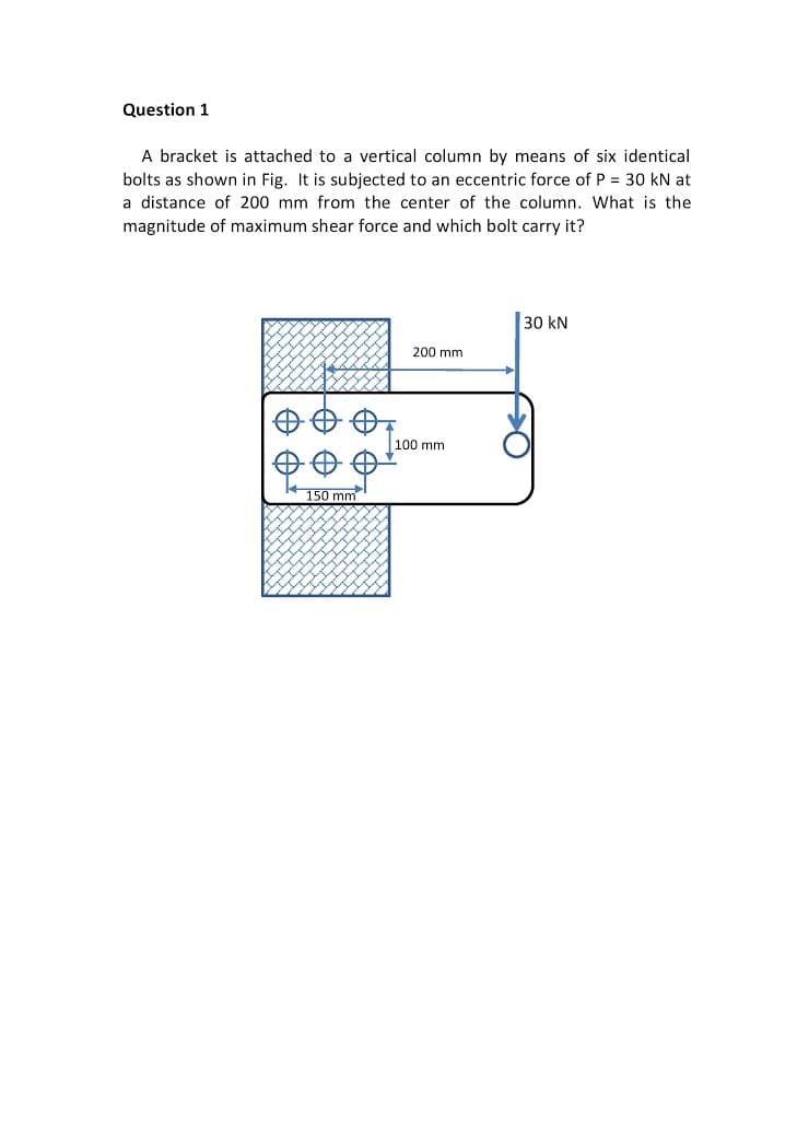
A bracket is attached to a vertical column by means of six identical bolts as shown in Fig. It is subjected to an eccentric force of P = 30 kN at a distance of 200 mm from the center of the column. What is the magnitude of maximum shear force and which bolt carry it?
Q: A solid circular bar is surrounded by a layer of copper rigidly attached to it, the assembly is…
A:
Q: A bicycle chain consists of a series of small links, where each is 12 mm long between the centres of…
A:
Q: Consider the truss shown in (Figure 1). Suppose that F = 60 kN and F2 = 30 kN. !! Figure < 1 of 1 50…
A:
Q: The cable and boom shown in the figure support a load of 600 lb. Determine the tensile force, T, in…
A:
Q: AB and CD caps of the same material are tightly fitted on both ends of the 24 mm diameter AD steel…
A: Given: E = 200 GPa LAB = 48 mm LBC = 72 mm LCD = 48 mm DAB = 36 mm…
Q: In a cruise ship, a liferaft is hanged by suspending it with a thick metallic cable attached to both…
A: Given, Tension in the cable , T = 40 KN Maximum allowable shear stress = 50 * 106 Pa
Q: a) Figure Q4 (a) shows an L-bracket ABC with diameter d which lies in the horizontal plane. It is…
A:
Q: A member is formed by connecting two steel bars shown below. Assuming that the bars are prevented…
A: Given, H1=7cm=0.07mH2=9cm=0.09m Area of top bar R=3×3 cm=9×10⁻⁴m2Area of bottom bar…
Q: Two steel wires support a movable overhead camera weighing W=25lb (see figure) used for close-up…
A: Data given-
Q: Solve the following problems The composite bar in the figure is made of two segments AB and BC,…
A: GivenF2=40 kNF1=171 kNd1=12 mm=12×10-3md2=8 mm=8×10⁻³mEAB=90 GPaEBC=80GPa
Q: The system shown is made up of an ABG bar, supported by a pin at point A and by a smooth coll al…
A:
Q: A tensile load of 40 kN is acting on a rod of diameter 40 mm and of length 4 m. A bore of diameter…
A: Given: Tensile load P=40 KN Diameter of the rod D=40 mm Area of the road A=π4D2…
Q: A 7.5kg sign is hung off of the end of a 3.7kg metal arm as shown in the figure. (Note that while…
A: Given Data: The mass of the arm is m1=3.7 kg. The mass of the sign is m2 = 7.5 kg. The center of…
Q: A circular tube is subjected to torsion by torques T applied at the ends. The bar is 0.75 m long and…
A: The length of the bar is, L=0.75 m The inside diameter of the bar is, d=35 mm The outside diameter…
Q: A spherical pressure vessel is constructed by bolting two hemispheres together along rigid flanges…
A: In the given questions, part (3) is entirely different problem. Hence, I am solving only 1 & 2…
Q: Example: Body M shown in figure weighs (300 N) and the homogeneous bar BE weighs (60 N). Draw the…
A:
Q: The 1.5 kN vertical OA pole is supported as shown in the figure and loaded with a horizontal force…
A: Given: The weight of the pole is 1.5 kN. The pole with the supported load is shown below:
Q: As shown in Fig, there is a gap between the aluminum bar and the rigid slab that is supported by two…
A: Given data as per question Area of copper rod =500 mm2 Area of aluminium rod =400 mm2 we know that…
Q: A pulley is keyed to a shaft midway between two anti-fiction bearings. The bending moment at the…
A:
Q: block is 4 inches long in the x direction, 2 inches long in the y direction, and 3 inches long in…
A:
Q: 1.2-10 A car having a mass of 5500 kg is pulled slowly up a steep inclined track by a steel cable…
A:
Q: The figure below shows a symmetric T-section that is subjected to a linearly varying distributed…
A: In this problem, it is asking about the equivalent force of the given distributed load.
Q: The force induced in member Q.3) PQ due to load W in figure will be
A:
Q: a)Consider the cable supporting the hook, and thus the load. The magnitude of the internal force…
A: Given: To Find: a) Consider the cable supporting the hook, and thus the load. The magnitude of the…
Q: Problem 4. The structure in the figure is composed of two rigid bars (AB and CD) and two vertical…
A: The free-body diagram of the beam is as shown below, Assumption: Let the length of aluminum and…
Q: A car weighing 130 kN when fully loadedis pulled slowly up a steep inclined track by asteel cable…
A:
Q: A member is formed by connecting two steel bars shown below. Assuming that the bars are prevented…
A:
Q: 2. A horizontal bar of negligible mass, hinged at A in the figure and assumed rigid, is supported by…
A: RS, RB are tensions in steel and bronze Rax and Ray are the rections at pin joint A ∆S ,∆B are…
Q: "P" that will cause the total length of the member to decrease 0.66 mm the values of elastic modulus…
A:
Q: Figure Q4 (a) shows an L-bracket ABC which lies in the horizontal plane. It is made from a material…
A: Disclaimer: Since you have posted multiple questions we will solve the first question for you. If…
Q: A member is formed by connecting two steel bars shown below. Assuming that the bars are prevented…
A:
Q: The composite bar in Fig. P-247 is stress-free before the axial loads P₁ applied. Assuming that the…
A: Given data as per questionP1=150 kNP2=90 kNFor Aluminium,1L1=500 mm=0.5mA1=900 mm2E1=70 GPaFor…
Q: Assuming the pulley system below is weightless and frictionless pulley (see below), if the load of…
A: Solution:
Q: The figure shows a setup where when the member AB is horizontal and the unstretched aluminum bar…
A:
Q: Problem 2. Each segment of bar ABC has length Z. and shear modulus G and both segments have solid…
A:
Q: The system of two springs shown below is loaded by a force F = 200 N and the result is a deformation…
A: Given data F = 200 N s = 3mm C1 = 2.5C2 To determine Overall stiffness of the system
Q: A uniform stone slab weighs 400 lb and is suspended by 3 cables and subjected to a downward vertical…
A:
Q: Solve the problem stated below. Use bond papers and black ball pen. Make your solution clear and…
A:
Q: n the figure, torsional moments act on a bar system of abruptly changing cross-section made of the…
A:
Q: The basic elements of a hydraulic press are shown in the figure below. The plunger has an area of 1…
A:
Q: A homogeneous 800 kg bar AB is supported at either end by a cable. Calculate the smallest area of…
A: Given:m=800 kgσb=90 MPaσs=120 MPa
Q: the system in the figure, the yield strength of the AB bar is 140 MPa and the diameter is 25 mm.…
A:
Q: Problem 2. Each segment of bar ABC has length Z. and shear modulus G and both segments have solid…
A:
Q: The bars AB, AC, and AD are pinned together as shown in the Horizontal movement of the pin at A is…
A:
Q: The uniform 300-1b bar AB carries a 500-lb vertical force at A. The bar is supported by a pin at B…
A:
Q: the figure is a b0x with weight W supp0rted by cables at B and C If the maximum stress in either…
A:
Q: A member is formed by connecting two steel bars shown below. Assuming that the bars are prevented…
A:
Q: A rectangular block is 6 in. long in the x – direction, 4 in. long in the y – direction, and 7 in.…
A:
Step by step
Solved in 4 steps with 4 images
- A vertical pole consisting of a circular tube of outer diameter 5 in. and inner diameter 4.5 in. is loaded by a linearly varying distributed force with maximum intensity of q0, Find the maximum shear stress in the pole.A flying but tress transmit s a load P = 25 kN, acting at an angle of 60º to the horizontal, to the top of a vertical buttress AB (see figure). The vertical buttress has height h = 5.0 m and rectangular cross section of thickness t = 1.5 m and width b = 1.0 m (perpendicular to the plane of the figure). The stone used in the construction weighs y = 26 kN/m3. What is the required weight W of the pedestal and statue above the vertical buttress (that is, above section A) to avoid any tensile stresses in the vertical buttress?A steel bar has a square cross section of width b = 2.0 in. (sec figure). The bar has pinned supports at the ends and is 3.0 ft long. The axial forces acting at the end of the bar have a resultant P = 20 kips located at distance e = 0,75 in, from the center of the cross section. Also, the modulus of elasticity of the steel is 29,000 ksi. Determine the maximum compressive stress max, in the bar. If the allowable stress in the steel is 18,000 psi, what is the maximum permissible length Lmaxof the bar?
- Solve the preceding problem (W 250 × 44.8) if the resultant force P equals 110 kN and E = 200 GPa.The figure shows an idealized structure consisting of rigid bars ABC And DEF joined by a linearly elastic spring ß between C and D. The structure is also supported by translational elastic support ß at B and rotational elastic support ßRat E. Determine the critical load Pcrfor the structure.A sign of weight W is supported at its base by four bolls anchored in a concrete footing. Wind pressure P acts normal to the surface of the sign; the resultant of the uniform wind pressure is force fat the center of pressure (C.P). The wind force is assumed to create equal shear forces F/4 in the y direction at each boll (see figure parts a and c). The overturning effect of the wind force also causes an uplift force R at bolts A and C and a downward force (— R) al bolts B and D (see figure part b). The resulting effects of the wind and the associated ultimate stresses for each stress condition are normal stress in each boll (h — 60 ksi); shear through the base plate (th = 17 ksi); horizontal shear and bearing on each bolt ( tfur = 25 ksi and cr^ = 75 ksi): and bearing on the bottom washer at B (or D) (abor = 50 ksi).
- A 10-ft rigid bar AB is supported with a vertical translational spring at A and a pin at B. The bar is subjected to a linearly varying distributed load with maximum intensity q0. Calculate the vertical deform at ion of the spring if the spring constant is 4 kips/in..17 A mountain-bike rider going uphill applies torque T = Fd(F = l5lb, d = 4 in.) to the end of the handlebars ABCD by pulling on the handlebar extenders DE. Consider the right half of the handlebar assembly only (assume the bars are fixed at the fork at A). Segments AB and CD are prismatic with lengths L, = 2 in.andL3 = 8.5 in, and with outer diameters and thicknesses d01 = 1.25 in. 101 = 0.125 in. and d03 = O.87in.,i03 = 0.ll5in, respectively as shown. Segment BC’ of length L, = 1.2 in. however. is tapered, and outer diameter and thickness vary linearly between dimensions at B and C. Consider torsion effects only. Assume G = 4000 ksi is constant. Derive an integral expression for the angle of twist of half of the handlebar tube when it is subjected to torque T = Fd acting at the end. Evaluate ‘b1-, for the given numerical1ues.A steel column ( E = 30 X 103 ksi) that is fixed at the base and free at the top is constructed of a W8 x 35 wide-flange member (sec figure). The column is 9.0 ft long. The force P acting at the top of the column has an eccentricity e = 1.25 in. If P = 40 kips, what is the maximum compressive stress in the column? If the yield stress is 36 ksi and the required factor of safety with respect to yielding is 2.1, what is the allowable load Pallow?
- Slender column ABC is supported at A and C and is subjected to axial load P. Lateral support is provided at mid-height if but only in the plane of the figure; lateral support perpendicular to the plane of the figure is provided only at ends A and C. The column is a steel W shape with modulus of elasticity E = 200 GPa and proportional limit pl= 400 MPa. The total length of the column L = 9 m. If the al low-able load is 150 kN and the factor of safety is 2.5, determine the lightest W 200 section that can be used for the column. (See Table F-l(b), Appendix F).An aluminum tube AB with a circular cross section has a sliding support at the base and is pinned at the top to a horizontal beam supporting a load Q = 200 kN (sec figure). Determine the required thickness t of the tube if its outside diameter d is 200 mm and the desired factor of safety with respect to Eu 1er buckling is n = 3.0. (Assume E = 72 GPa.)A sign for an automobile service station is supported by two aluminum poles of hollow circular cross section, as shown in the figure. The poles are being designed to resist a wind pressure of 75 lb/ft" against the full area of the sign. The dimensions of the poles and sign are hx= 20 ft, /r =5 ft, and h = 10 ft. To prevent buckling of the walls of the poles, the thickness e is specified as one-tenth the outside diameter d. (a) Determine the minimum required diameter of the poles based upon an allowable bending stress of 7500 psi in the aluminum. (b) Determine the minimum required diameter based upon an allowable shear stress of 300 psi.