A uniform stone slab weighs 400 lb and is suspended by 3 cables and subjected to a downward vertical loa as shown in the figure and parameter table. A


Q: The L-bar shown in the figure is fastened by a bearing at point A that allows it to rotate, such…
A: Given F=800NRBmax=600N
Q: A non-uniform bar weighs 400N and is 4m long. When it is supported by a fulcrum at its midpoint, a…
A: Consider the free body diagram as shown below for the uniform bar.
Q: 7. In the wedge shown in the figure. Determine the largest angle that will cause the wedge to be…
A: As per given question We have to determine the largest angle
Q: Q2 : The three bars shown in fig are pined at point B which carry a load P and fixed at points A, C…
A: Given: Three bars AB, BD ad CB Cross section of AB=BD=A1 and CB= A2 Young's Modulus of all the bars…
Q: Consider the frame shown in Fig 4. A 100N load is suspended around a fixed drum with radius 2 m…
A:
Q: The figure above illustrates a system comprising a rigid support structure having a cross-sectional…
A:
Q: Q: The two-steel shaft shown in figure have the same diameter and weight 140 lb each. Neglect the…
A:
Q: In the figure shown, the rigid bar with negligible mass was horizontal before the load P was…
A:
Q: The rigid arm of negligible weight shown in the figure supports a load of F = 852 N. The chains are…
A: Given data: F=852 Nx1=5 mx2=4 my=7 mz=5 m Need to determine the Magnitude of the force in FBE.
Q: The mechanism in the figure below is designed to maintain the horizontal position of the load while…
A: Given values a=34cm, b=68cm, c=20cm, r=93cm, m=110kg Given figure
Q: Q.4) The rope pulley arrangement shown in Figure is under equilibrium. Find the value of weight W.…
A:
Q: 13)The Beam in figure below is weightless. A moveable weight(mass)W of 300 Ibm is to be attached as…
A:
Q: 70 in - 36 in - y 20 in 3300 lb
A: 1) As given in question rear wheels are locked and front are free to turn so we can consider front…
Q: 3-81: Figure P3-81 shows two rods, AB and BC, supporting a load at B. Each rod is steel and has a…
A: Given Data,
Q: ) In the Figure, the of ylinder A is 4m, cylinder Sm. Neglecting priction, a) solve radius is Gm,…
A: for the given system rA = 4 m rB = 6 m rc = 5 m To determine (A) the reaction between A and B…
Q: A girder shown in the following figure is supported by two cables. The weight of the girder is 8000…
A: For the given girder Weight of girder (W) = 8000 lb To determine The tension in both cable and…
Q: Example: Body M shown in figure weighs (300 N) and the homogeneous bar BE weighs (60 N). Draw the…
A:
Q: The 1.5 kN vertical OA pole is supported as shown in the figure and loaded with a horizontal force…
A: Given: The weight of the pole is 1.5 kN. The pole with the supported load is shown below:
Q: 3a)Two cylinders each of diameter 100 mm and each weighing 200 N are placed as shown in figure…
A:
Q: Figure Q2 shows a shaft consists of Rods AB, BC and CD which made of Aluminium, Brass and Steel,…
A:
Q: Q The two-steel shaft shown in figure have the same diameter and weight 180 lb each. Neglect the…
A: Given, Weight = 180 lb
Q: A 15,000 N crane pivots around a friction-free axle at its base and is supported by a cable making a…
A: a.
Q: The rigid bars AB and CD shown in Figure below are supported by pins at A and C and the two rods.…
A: For the aluminum cable, Length of the Aluminum, LAl=2m=2000 mm Area of the aluminum, AAl=500mm2…
Q: 1. The ladder shown in Figure rests on a horizontal floor and vertical wall. The weight of the…
A:
Q: Find the tension I required in the operating wire to raise the signal arm through the system of…
A:
Q: -1m 1m Ql: A: Draw a Free-Body Diagram of the bars AD and BC shown in the figure. Assume all hinges…
A:
Q: Q The two-steel shaft shown in figure have the same diameter and weight 170 lb cach. Neglect the…
A:
Q: Example: Body M shown in figure weighs (300 N) and the homogeneous bar BE weighs (60 N). Draw the…
A:
Q: A horizontal L=1.2 m long mb=14 kg uniform bar is hinged on the left end and pulled at the right end…
A:
Q: Q4: An inclined circular gate (AB) with hinge support at (B) and the weight of gate (12KN).…
A:
Q: Figure Q2 shows a shaft consists of Rods AB, BC and CD which made of Aluminium, Brass and Steel,…
A:
Q: P-1500 kg 45 Py-4000kg k P:
A:
Q: The wooden pile shown in the figure has a diameter of 120 mm and is subjected to a load of P = 80…
A:
Q: 5.1.11 In the following structures, a pin connects two thin bars that are very nearly either…
A:
Q: The structure OABC shown in Figure Qle are connected using ball-and-socket joint at O and bearing at…
A:
Q: find the value of R1
A: Given: weight of the Carriage (W1) =480 lb Weight of the ladder (W2) =240 lb P= 180 lb Distance…
Q: A uniform rod of weight mg and length L is in equilibrium on a frictionless support as shown in the…
A:
Q: 1. A rigid horizontal bar of negligible mass is connected to two rods as shown in the figure. If the…
A:
Q: Two identical rollers, each of weights W=1000N, are supported by an inclined plane and a vertical…
A:
Q: Perfectly smooth W=240 lb 5' 5' .A 4. 1' C 3.
A: Consider the free body diagram:
Q: The homogeneous bar shown in Fig. P-106 is supported by a smooth pin at C and a cable that runs from…
A:
Q: 8. Calculate the horizontal reaction at O in Fig Q8 due to the load P = 177 N applied to the bar OB.…
A:
Q: Problem 1: The T-shaped arm ABC shown in the figure lies in a vertical plane and pivots about a…
A: Free body diagram:
Q: The basic elements of a hydraulic press are shown in the figure below. The plunger has an area of 1…
A:
Q: Question: The truss, shown in the Figure, is subjected to the weight W and supported by the pins…
A:
Q: The system shown is composed of an ABG bar, supported by a pin at point A and by a collar smooth at…
A:
Q: For the suspended load F = 637lb in the figure. Find the magnitude of the reaction of the patella at…
A: Given data, Suspended load, F= 637 lb The coordinates of O = (0, 0, 0) The coordinates of A = (8, 6,…
Q: Q The two-steel shaft shown in figure have the same diameter and weight 150 lb cach. Neglect the…
A:
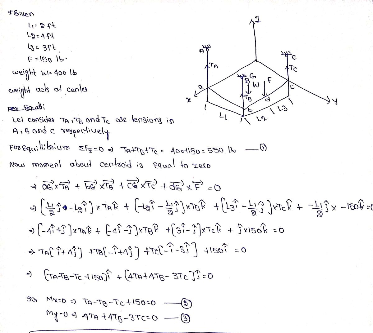
Q: A uniform stone slab weighs 400 lb and is suspended by 3 cables and subjected to a downward vertical…
A: From the moment about the x-axis,


Trending now
This is a popular solution!

Step by step
Solved in 2 steps with 2 images


- A cylindrical brick chimney of height H weighs w = 825 lb/ft of height (see figure). The inner and outer diameters are d1= 3 ft and d2= 4 ft, respectively. The wind pressure against the side of the chimney is p = 10 lb/ft2 of projected area. Determine the maximum height H if there is to be no tension in the brickwork.A 150-lb rigid bar AB. with friction less rollers al each end. is held in the position shown in the figure by a continuous cable CAD. The cable is pinned at C and D and runs over a pulley at A. (a) Find reactions at supports A and B. (b) Find the force in the cable.Solve the preceding problem for W = 1.0 lb. h = 12 in.,and k =0.511,/in.
- A hollow circular pipe (see figure} support s a load P that is uniformly distributed around a cap plate at the top of the lower pipe. The inner and outer diameters of the upper and lower parts of the pipe are d1= 50 mm, d2= 60 mm, rf3 = 57 mm, and d1= 64 mm, respectively. Pipe lengths are Lt= 2 m and L, = 3 m. Neglect the self-weight of the pipes. Assume that cap plate thickness is small compared to I, and E,. Let E = 110 MPa. (a) If the tensile stress in the upper part is d = 10.5 MPa. what is load PI Also, what are reactions ft, at the upper support and R-, at the lower support? What is the stress ar(MPa) in the lower part? (b) Find displacement S(mm) at the cap plate. Plot the axial force diagram (AFD) [Ar(.f)] and axial displacement diagram (ADD)[5(.t)]. (c) Add the uniformly distributed load q along the censorial axis of pipe segment 2. Find q (kN/m) so that It, = 0. Assume that load P from part (a) is also applied.By what distance h does the cage shown in the figure move downward when the weight W is placed inside it? (See the figure.) Consider only the effects of the stretching of the cable, which has axial rigidity EA = 10,700 kN. The pulley at A has a diameter da= 300 mm and the pulley at B has a diameter dB= 150 mm. Also, the distance L1= 4.6 m, the distance L2=10.5 m, and the weight W = 22 kN. Note: When calculating the length of the cable. include the parts of the cable that go around the pulley sat A and B.The L-shaped arm ABCD shown in the figure lies in a vertical plane and pivots about a horizontal pin at A. The arm has a constant cross-sectional area and total weight W. A vertical spring of stiffness k supports the arm at point B. (a) Obtain a formula for the elongation of the spring due to the weight of the arm. (b) Repeat part (a) if the pin support at A is moved to D.
- Two separate cables AC and BC support a sign structure of weight W = 1575 lb attached to a building. The sign is also supported by a pin support at O and a lateral restraint in the '-direction at D. (a) Find the tension in each cable. Neglect the mass of the cables. (b) Find the average stress in each cable if the area of each cable is Ae= 0.471 in2.A bungee jumper having a mass of 55 kg leaps from a bridge, braking her fall with a long elastic shock cord having axial rigidity EA = 2.3 kN (see figure). If the jumpoff point is 60 m above the water, and if it is desired to maintain a clearance of 10 m between the jumper and the water, what length L of cord should be used?A safety valve on the top of a tank containing steam under pressure p has a discharge hole of diameter d(see figure). The valve is designed to release the steam when the pressure reaches the value Pmax If the natural length of the spring, is L and its stiffness is k, what should be the dimension ft of the valve? (Express your result as a formula for h.)
- A uniform bar AB of weight W = 25 N is supported by two springs, as shown in the figure. The spring on the left has a stiffness k[= 300 N/m and natural length Lt=250 mm. The corresponding quantities for the spring on the right are k2= 400 N/m and L^ = 200 mm. The distance between the springs is L = 350 mm, and the spring on the right is suspended from a support that is a distance it = SO mm below the point of support for the spring on the left. Neglect the weight of the springs. (a) At what distance x from the left-hand spring (figure part a) should a load P = 18 N be placed in order to bring the bar to a horizontal position? (b) If P is now removed, what new value of k{is required so that the bar (figure part a) will hang in a horizontal position underweight If? (c) If P is removed and kt= 300 N/m. what distance b should spring ktbe moved to the right so that the bar (figure part a) will hang in a horizontal position under weight II"? (d) If the spring on the left is now replaced by two springs in series (kt= 300 N/m, kt) with overall natural length Lt= 250 mm (see figure part b). what value of k; is required so that the bar will hang in a horizontal position under weight IF?.15 A hitch-mounted bicycle rack is designed to carry up to four 30-lb bikes mounted on and strapped to two arms Gil (sec bike loads in the figure part a) The rack is attached to the vehicle at A and is assumed to be like a cant silkier beam A BCDGII (figure part b) The light of fixed segment AB is U = 10 lb. centered 9 in. from A (see figure part b) and the rest of the rack highs W2 = 40 lb. centered 19 in. from A. Segment ABCDG is a steel tube o(2 X 2 in. with a thickness I = 118 in. Segment BCDGII pivots about a bolt at B with a diameter d1 = 0.25 in. to allow access to the rear of the vehicle without removing the hitch rack. When in use, the rack is secured in an upright posit ion by a pin C(diameter o( pin d, = 5116 in.) (see phoo and figure part C). The of returning effect of the bikes on the rack is resisted by a force couple F h at BC. (a) Find the support reactions at A for the fully loaded rack. (b) Find forces in the bolt at B and the pin at C. (c) Find average shear stresses in both the bolt at Band the pin at C. (d) Find average bearing stresses o, in the bolt at B and the pin at C.A steel post (E=30×106) having thickness t = 1/8 in. and height L = 72 in. support a stop sign (see figure), where s = 12.5 in. The height of the post L is measured from the base to the centroid of the sign. The stop sign is subjected to wind pressure p = 20 lb/ft2 normal to its surface. Assume that the post is fixed at its base. What is the resultant load on the sign? (Sec Appendix E, Case 25, for properties of an octagon, n =8.) What is the maximum bending stress in the post? Repeat part (b) if the circular cut-outs arc eliminated over the height of the post.