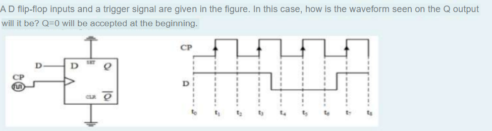
A D flip-flop inputs and a trigger signal are given in the figure. In this case, how is the waveform seen on the Q output will it be? Q=0 will be accepted at the beginning. CP SET D D e CP D CLR To


Q: Electrical Circuits / I need a correctly hand-drawn expert solution.
A: Step 1:Step 2:Step 3:Step 4:
Q: I = 5.76mA∠43.91° VR = IZR = (5.76mA∠43.91°)(1kΩ∠0°) = 5.76V∠43.91° VL = IZL =…
A: Step 1:
Q: Please answer in typing format
A: In electrical installations, it's crucial to adhere to safety standards to prevent potential…
Q: thank u
A: Step 1:Step 2:
Q: Provide complete solution of the given problem in the image.
A: Step 1:
Q: A bipolar transistor is connected to a resistive load. The source voltage is 40 volts, the load…
A: Given data,Voltage Source, VCC = 40VLoad resistance, RL = 10ΩCollector emitter voltage, VCE =…
Q: None
A:
Q: Please answer in typing format
A: all questions are Answered in the answer section.. thank you..
Q: Can you please show me how to use the K map to simplify boolean expressions for f2,f1, and fo? A B C…
A: Step 1:Step 2:
Q: Vll=164v IL=0.48A P1=75W P2=75W Pinput=150w please solve question 5 in discussion section
A: Step 1:Step 2:Step 3:
Q: Question No. 4: (handwritten) a) Use Dynamic CMOS level design technique to prepare a 4 input NAND…
A: The objective of this question is to design a 4-input NAND gate using two different design…
Q: Exercise 5 Find 11, 12 and ID2 in the circuit below. E 20 V 2 D1 Si ID2 R₁ R₂ D2 ▼ Si V₁ 3.3 ΚΩ 5.6…
A: Step 1: Basic concept Step 2: Solution page 1Step 3: Solution page 2
Q: PART II-CIRCUIT DESIGN So, you work for a company that fabricates prototypes of a variety of…
A: Step 1:Step 2: Step 3:Step 4:
Q: Communication system Consider a communication channel with a spectrum between 5 MHz and 7 MHz and…
A: Let us consider an example that relates the Nyquist and Shannon formulations. Suppose that the…
Q: Find v0 if it is 20 V using source transformations.
A: Step 1: Step 2: Step 3: Step 4:
Q: Using Mesh Analysis for Figure 4 (a) Calculate the voltages vo and io of the circuit, as well as the…
A: Step 1: Step 2: Step 3: Step 4:
Q: 6. The instantaneous value of an alternating current is 5 mA at a displacement angle of 60°.…
A: Step 1: Step 2: Step 3: Step 4:
Q: 02: Using the following discrete sequence definitions -2 x(n) = =1 0 and n = 0,1,2 n = 3,4 elsewhere…
A: In the question it's mention that choose any TWO.so I did by choosing two methods.
Q: Using Kirchhoff's Theorem, write the complete, but SIMPLIFIED loop equation for LOOP 1 (May use…
A: Kindly see attached photo for your guidance.
Q: (a) Find an expression for vo (t) fort > 0 in the circuit shown in Fig. 4 (a). 20 6 Ո 10 www www www…
A: Step 1: Step 2: Step 3: Step 4:
Q: I had asked this question, but i am not sure if it got picked up, if you can solve this it would be…
A: Step 1Step 2 Step 3 Step 4
Q: how do i solve this without using Laplace transform? instead solving differential equations..... if…
A:
Q: 4. Calculate the average output value of a fully controlled 24-pulse thyristor converter feeding…
A:
Q: A 2-MVA, 4400-V, 25-Hz, Y-connected, three-phase, synchronous generator is tested at its rated speed…
A:
Q: Electrical plants Define the terms "Main column ." " Line ." " Protection earth " and " Operating…
A: 1. Main Column:It refers to a primary or main electrical distribution line or column within a power…
Q: Using mesh analysis please show how to determine the current i10 if it is -2.29 A.
A:
Q: 1- P-Controller 2- Pl-Controller 3- PID-Controller Notes: e(s) V(s) K {(Js+b)(Ls+R)+K2}s **For the…
A: Step 1:It seems like you're conducting experiments and simulations related to designing controllers…
Q: Question No. 1: (Need handwritten, Don't Send AI Answer) a) Explain why NMOS passes strong 0 and…
A: The NMOS and PMOS transistors are the basic building blocks of digital circuits. NMOS transistor…
Q: 3. The 6-V zener diode in Fig. 7-12 has a maximum rated power dissipated of 690 mW. Its reverse…
A: Here's explanation:
Q: show all the work
A: Step 1:Step 2:
Q: 11. A microprocessor in a 0.25 μm process was observed to have an average D2D variation of 8.99 %…
A: Based on the image you sent, the question asks to solve for the clock period required to ensure a…
Q: Please answer in typing format
A: Step 1:pole = 6In block rotor test the wattmeter indicates only the copper loss…
Q: As shown in the following figure, a network connecting the end points A and D has five links. The…
A: Step 1: Consider two cases, Link 5 is in success and Failed state.Step 2: Case 1: Link 5 is in…
Q: ww Vos 201 D 15 V 1.5 K Ohm 7.5 V 4 V 5.75 V 5 V A B
A: based on your description that it's a circuit for measuring the voltage across a load (VL) and the…
Q: Communication system Let's consider a communication system where four signals with different…
A: Step 1:Step 2:
Q: Please answer in typing format
A: The voltage across the capacitor is V(t)=(1/C)∫idtGiven capacitor value C=2.3F. From the current…
Q: The inputs are A and B. Convert this diagram to an alphanumeric state diagram.
A: Imagine a machine that can be in specific situations and reacts differently based on what it…
Q: what is true about asynchronous motors?A) asynchronous motor is more expensiveB) an electric arc…
A: Asynchronous motors (also known as induction motors) are prevalent in industrial applications due to…
Q: The frequency of the sinusoidal voltage source in the circuit in (Figure 1) is adjusted until the…
A: Step 1:Step 2:Why the term 'obviously'?Since we are keeping w=10 which makes the imaginary term 0 at…
Q: Review purpose only/ Show solution please! thanks!
A: Step 1: Step 2: Step 3: Step 4:
Q: please solve this question detailed step by step solution thank you
A: Step 1:
Q: B) Consider the meter indications in each circuit bellow, and determine whether the diode is…
A:
Q: We have a electric circuit of current (i) in a series R-L, the current is given by the following:…
A: Accuracy of Both MethodsBoth methods yield the same solution for i(t), which is i(t)= 4−4e-5t .…
Q: A, B, C are the inputs, and D, E, F are the outputs. By “completely specified” it means that, for…
A: Let's analyze the state graph and construct the corresponding state table. 1. State Graph…
Q: A 3- ac motor is connected to 125 Vac lint to neutral 3- 60 Hz from which it draws 22A line current…
A: Step 1: Step 2: Step 3: Step 4:
Q: Calculate the period of g(t) = sgn(sin(4mt)) + sin(18πt). Your answer shouldn't exceed a few…
A: The period of a function is the smallest positive value of T for which g(t + T) = g(t) holds for all…
Q: [Q2] What is the power (S) required at the receiver to achieve a channel capacity of 550kbps? Assume…
A: Step 1: Step 2: Step 3: Step 4:
Q: Figure 1 shows a layout implemented in the 45 nm CMOS process described in the information sheet…
A: According to the question, for the given CMOS layout as shown belowFor each of the three items,…
Q: Using the figure, if the frequency of V1 was 1.9 kHz and L1 was 10 mH, what would the reactance of…
A: Approach to solving the question:The reactance of an inductor is given as: X=j2πfL•So magnitude is:…
Q: x(t) = (A+m(t)) cos(100πt) m(t) is a low-pass signal with B<<50. A=10. Write down Fourier transform…
A: Step 1: Step 2: Step 3:

Step by step
Solved in 2 steps with 1 images

- Show the digital circuit diagram, output waveforms and truth table of a modulo-5 up counter using toggle flip-flops and explain the working principle.Design the asynchronous counter circuit using JK flip-flops, starting from the smallest decimal digit to the largest decimal digit in the following numbers. (1180501624)Question Vv Design a synchronous counter using a J-K Flip-flop with an irregular binary count sequence shown in the state diagram.
- Assume that there is a flip-flop with thecharacteristic given in Figure, where A and Bare the inputs to the flip-flop and Q is the next stateoutput. Using necessary logic gates, make a T flip-flopfrom this flip-flop.Design a Mode 14 asynchronous forward counter circuit. (Use JK or T type flip-flops) I designed the mode 11 forward counter circuit below (using JK or T type flip-flop) Can you draw a Mod 14 asynchronous forward counter circuit as in the photo?design a 3-bit ring counter using D flip flops draw the logic diagram
- A binary pulse counter can be constructed byinterconnecting T-type flip-flops in an appropriatemanner. Assume it is desired to construct a counterwhich can count up to 10010. a. How many flip-flops would be required?b. Sketch the circuit needed to implement this counter.2- Consider a state diagram shown below. Implement this state diagram using T (toggle) flip-flops and AND gates. What is the purpose of the circuit?Complete the design process using full encoding and D-flip flop for the the function described by the follow state diagram and draw the schematics.
- Using two flip-flops and basic gates, construct the circuit of the given state diagram below. Provide the following: State Table, Flip-flop equations, Circuit DiagramCompare the circuits, characteristic tables, and the timing diagrams of SR Flip-flops, JK flip-flops, and D flip flops. In your own words, describe the similarity and differences in behavior of these flip flops. Then go on to make comparison between Mealy and Moore machines, first describe each FSM and then elaborate on the similarity and differences between them.Digital Logic Design Design a BCD ripple up counter using positive edge trigger J-K flip-flops.