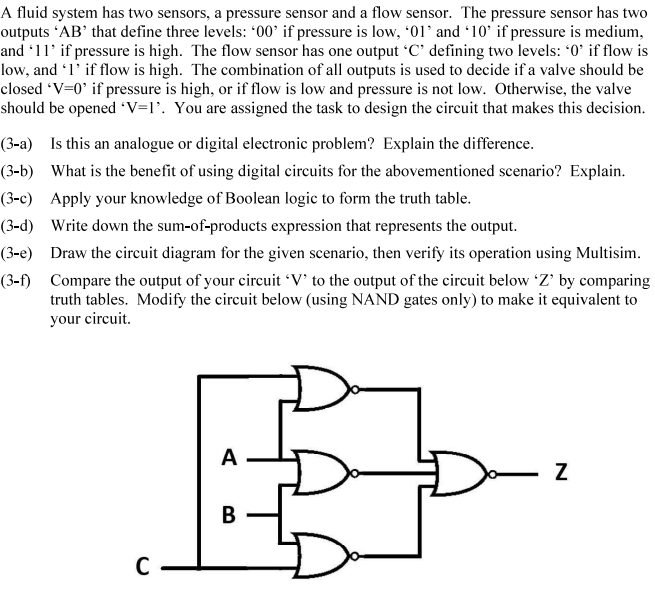
A fluid system has two sensors, a pressure sensor and a flow sensor. The pressure sensor has two outputs ‘AB' that define three levels: '00' if pressure is low, '01' and '10' if pressure is medium, and '11' if pressure is high. The flow sensor has one output 'C' defining two levels: '0' if flow is low, and '1' if flow is high. The combination of all outputs is used to decide if a valve should be closed *V=0' if pressure is high, or if flow is low and pressure is not low. Otherwise, the valve should be opened *V=I'. You are assigned the task to design the circuit that makes this decision. (3-a) Is this an analogue or digital electronic problem? Explain the difference. (3-b) What is the benefit of using digital circuits for the abovementioned scenario? Explain. (3-c) Apply your knowledge of Boolean logic to form the truth table. (3-d) Write down the sum-of-products expression that represents the output. (3-e) Draw the circuit diagram for the given scenario, then verify its operation using Multisim. (3-f) Compare the output of your circuit 'V' to the output of the circuit below 'Z' by comparing truth tables. Modify the circuit below (using NAND gates only) to make it equivalent to your circuit.
A fluid system has two sensors, a pressure sensor and a flow sensor. The pressure sensor has two outputs ‘AB' that define three levels: '00' if pressure is low, '01' and '10' if pressure is medium, and '11' if pressure is high. The flow sensor has one output 'C' defining two levels: '0' if flow is low, and '1' if flow is high. The combination of all outputs is used to decide if a valve should be closed *V=0' if pressure is high, or if flow is low and pressure is not low. Otherwise, the valve should be opened *V=I'. You are assigned the task to design the circuit that makes this decision. (3-a) Is this an analogue or digital electronic problem? Explain the difference. (3-b) What is the benefit of using digital circuits for the abovementioned scenario? Explain. (3-c) Apply your knowledge of Boolean logic to form the truth table. (3-d) Write down the sum-of-products expression that represents the output. (3-e) Draw the circuit diagram for the given scenario, then verify its operation using Multisim. (3-f) Compare the output of your circuit 'V' to the output of the circuit below 'Z' by comparing truth tables. Modify the circuit below (using NAND gates only) to make it equivalent to your circuit.

Introductory Circuit Analysis (13th Edition)
13th Edition
ISBN:9780133923605
Author:Robert L. Boylestad
Publisher:Robert L. Boylestad
Chapter1: Introduction
Section: Chapter Questions
Problem 1P: Visit your local library (at school or home) and describe the extent to which it provides literature...

Related questions
Question
solustion of (3-c) & (3-d) only
Transcribed Image Text:A fluid system has two sensors, a pressure sensor and a flow sensor. The pressure sensor has two
outputs 'AB' that define three levels: '00' if pressure is low, '01' and '10' if pressure is medium,
and '11' if pressure is high. The flow sensor has one output 'C' defining two levels: '0' if flow is
low, and '1' if flow is high. The combination of all outputs is used to decide if a valve should be
closed 'V=0' if pressure is high, or if flow is low and pressure is not low. Otherwise, the valve
should be opened *V=1'. You are assigned the task to design the circuit that makes this decision.
(3-a) Is this an analogue or digital electronic problem? Explain the difference.
(3-b) What is the benefit of using digital circuits for the abovementioned scenario? Explain.
(3-c) Apply your knowledge of Boolean logic to form the truth table.
(3-d) Write down the sum-of-products expression that represents the output.
(3-e) Draw the circuit diagram for the given scenario, then verify its operation using Multisim.
(3-f) Compare the output of your circuit 'V' to the output of the circuit below 'Z' by comparing
truth tables. Modify the circuit below (using NAND gates only) to make it equivalent to
your circuit.
A
B
C
N
Expert Solution
This question has been solved!
Explore an expertly crafted, step-by-step solution for a thorough understanding of key concepts.

Step by step
Solved in 3 steps with 1 images

Knowledge Booster


Learn more about
Need a deep-dive on the concept behind this application? Look no further. Learn more about this topic, electrical-engineering and related others by exploring similar questions and additional content below.Recommended textbooks for you
Introductory Circuit Analysis (13th Edition)
Electrical Engineering
ISBN:
9780133923605
Author:
Robert L. Boylestad
Publisher:
PEARSON

Delmar's Standard Textbook Of Electricity
Electrical Engineering
ISBN:
9781337900348
Author:
Stephen L. Herman
Publisher:
Cengage Learning

Programmable Logic Controllers
Electrical Engineering
ISBN:
9780073373843
Author:
Frank D. Petruzella
Publisher:
McGraw-Hill Education
Introductory Circuit Analysis (13th Edition)
Electrical Engineering
ISBN:
9780133923605
Author:
Robert L. Boylestad
Publisher:
PEARSON
Delmar's Standard Textbook Of Electricity
Electrical Engineering
ISBN:
9781337900348
Author:
Stephen L. Herman
Publisher:
Cengage Learning
Programmable Logic Controllers
Electrical Engineering
ISBN:
9780073373843
Author:
Frank D. Petruzella
Publisher:
McGraw-Hill Education

Fundamentals of Electric Circuits
Electrical Engineering
ISBN:
9780078028229
Author:
Charles K Alexander, Matthew Sadiku
Publisher:
McGraw-Hill Education

Electric Circuits. (11th Edition)
Electrical Engineering
ISBN:
9780134746968
Author:
James W. Nilsson, Susan Riedel
Publisher:
PEARSON

Engineering Electromagnetics
Electrical Engineering
ISBN:
9780078028151
Author:
Hayt, William H. (william Hart), Jr, BUCK, John A.
Publisher:
Mcgraw-hill Education,