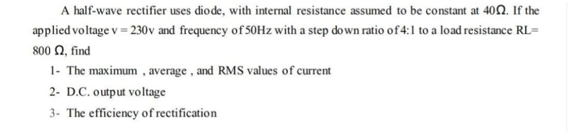
A half-wave rectifier uses dio de, with internal resistance assumed to be constant at 402. If the applied voltage v = 230v and frequency of 50HZ with a step down ratio of4:1 to a load resistance RL= 800 Q, find 1- The maximum , average, and RMS values of current 2- D.C. output voltage 3- The efficiency of rectification


Q: Problem (3) A half-wave rectifier as shown has a 240Vms, 60 Hz ac source. The load is a series…
A:
Q: For the following circuit, consider that both diodes D1 and D2 are ideal, that is VK = 0 V. Consider…
A: Analog electronics
Q: A half-wave rectifier circuit using an ideal diode has an input voltage of 10 sin wt V; find the…
A:
Q: Question 4) A full wave controlled rectifier with ohmic load given in the figure below feeds a 10 Q…
A: Peak value of voltage(Vm)=2×VrmsAverage value of voltage, V0=2VmπAverage value of Current,…
Q: 7 Full-Wave Rectification 28. A full-wave bridge rectifier with a 120-V rms sinusoidal input has a…
A: In this question full wave bridge rectifier is given...We have to find dc voltage at load ,PIV of…
Q: For the following circuit, consider that both diodes D1 and D2 are ideal, that is Vx = 0 V. Consider…
A:
Q: Ql: A half-controlled three-phase bridge rectifier is supplied at 220 V (RMS line voltage) from a…
A: A rectifier circuit is used to rectify the AC power generated by this source to the DC power that…
Q: Q4. In the full-wave diode rectifier shown below, the diodes are ideal. The source voltage is v, =…
A:
Q: Q.3: For a single-phase half-wave controlled rectifier supplies (RL) inductive load, if input source…
A:
Q: b. Partial specifications of a Zener diode is provided. Zener Voltage VZ = 10.0 V, VZK = 9.6 V, and…
A: Diode Voltage is, Vz=VZK+rZIZTrZ=Vz-VZKIZTrZ=10-9.650 mArZ=8 Ω
Q: A half wave rectifier with is given to an input of 10V peak from a step down transformer. Calculate,…
A: Half wave rectifier given in the circuit, Find the average current Average voltage and rectifier…
Q: Q1\ Draw the bridge full wave rectifier and explain the operation of each part in the circuit. Q2\…
A: Rectifier is a device which convert alternating signal in to pulsating direct signal. The diode is…
Q: A half wave diode rectifier with 4,700 uF smoothing capacitor connects a 50 2 resistive load to a 60…
A:
Q: Consider the following rectifier circuit with four ideal diodes and an ideal Thyristor. (a) Sketch a…
A: Given Circuit:
Q: Q4. In the full-wave diode rectifier shown below, the diodes are ideal. The source voltage is v, =…
A: GIVEN DATA:
Q: 3 A peak rectifier (peak follower) Cir cuit is given below. Vs is a GOH3 Sinusuidal Vollage with…
A: Given data, Vp=50 Vf=60 HzR=5 kΩVr=2 V
Q: V, is a 60Hz source with a peak voltage VP-120V is feeding a rectifier, assume ideal diode. The load…
A: Given circuit, Peak voltage, VP=120 V Load resistance, R = 10 kΩ Ripple voltage, Vr=2 V
Q: FB Q.3) The input voltage to a Full-wave rectifier employing a center - tapped step-down transformer…
A:
Q: sinusoidal voltage of 50 V (Vrms) and frequency 50 Hz is applied to a half wave rectifier. RL = 200…
A:
Q: 4. The circuits parameters for an uncontrolled full-wave rectifier are as follows: Vin rms = 20V w=…
A:
Q: A single phase – half wave controlled rectifier with freewheeling diode is supplying a load…
A: According to the question we have Define the load current expression and draw the load current by…
Q: 4.70 A full-wave bridge-rectifier circuit with a 500-2 load operates from a 120-V (rms) 60-Hz…
A: We need to analyse the given full wave rectifier circuit
Q: b) An unregulated dc power supply provides a dc voltage that can vary between 18 and 22 V. Design a…
A:
Q: A silicon diode having 20 Ω internal resistance is used as half wave rectifier. If the applied…
A:
Q: Q4) For the Zener regulated power supply shown below the rms value of vs is 15 V, the operating…
A: According to the question we have to find, Find Voutput & find the ripple voltage.
Q: Q1. For the full-wave controlled rectifier circuit shown below, the thyristors are fired at a…
A:
Q: 4.71 A full-wave rectifier circuit with a 1-k2 load operates from a 120-V (rms) 60-Hz household…
A:
Q: b. Partial specifications of a Zener diode is provided. Zener Voltage Vz = 5.0 V, VżK = 4.8 V, and…
A: Given that: Vz = 5.0 VzK = 4.8V Total zener current (IZT) =25mA Breakdown = 2 x (IZT) To Find :…
Q: 5. A single -phase, fully-controlled bridge rectifier supplies a constant current to a highly…
A: The single-phase fully controlled bridge rectifier with the constant current load a) Without the…
Q: V sin of For the following single-phase full-wave diode rectifier, Vm = 311 V, R = 1 N, L = 0.002 H…
A: The fundamental value of the source current is evaluated as:
Q: Design a half-wave rectifier power supply to deliver an average voltage of 9 V with a peak-to-peak…
A: Half wave Rectifier
Q: 4.70 A full-wave bridge rectifier circuit with a 1-k2 load operates from a 120-V (rms) 60-Hz…
A:
Q: A semiconductor diode having ideal forward and reverse characteristics is used in a half-wave…
A:
Q: 1. For the full-wave rectifier answer the following: Note: Treat diodes as ideal. A. Which diode(s)…
A:
Q: the given circuit, (diodes will be considered ideal. a) Draw the V0 output by calculating it…
A:
Q: 4.68 A half-wave rectifier circuit with a 1-k2 load oper- ates from a 120-V (rms) 60-Hz household…
A:
Q: 24 A 30-volt forward voltage is applied to a silicon diode in series with a load of 3 kf2. Draw the…
A:
Q: 28. A full-wave bridge rectifier with a 120-V rms sinusoidal input has a load resistor of 1 kſN. a.…
A: As per the guidelines of Bartley we supposed to answer first three subpart only for solution of…
Q: Consider a three-phase diode rectifier supplying a R = 10 Ω DC load. The supply system is 440 VLL…
A:
Q: Find the performance parameters (FF, RF and n) for the Single phase bridge uncontrolled rectifier…
A: A rectifier circuit is used to rectify the AC power generated by this source to the DC power that…
Q: A full wave rectifier with center-tapped transformer (10-0-10) supplies a load current of 100 mA to…
A:
Q: Design a Zener diode voltage regulator with a suitable circuit diagram and to consider the voltage…
A:
Q: A pure resistive R ohm is connected to the output of the three-phase Bridge Rectifier. resistor is…
A: We are authorized to answer three subparts at a time, since you have not mentioned which part you…
Q: 2. For the half-wave rectifier shown below, the cut-in voltage is 0.7 V. Sketch the voltage transfer…
A: Given circuit is a Half wave rectifier we have asked to solve vi,vii,viii,ix,x, Note: output we…
Q: A simple diode rectifier has 'ripples' in the output wave which makes it unsuitable as a DC source.…
A: correct option is D a capacitor in parallel to load resistance.
Q: 22. For the cIrcult shown In the figure below, assume that diodes D,, D, and D, are Ideal.…
A: Given circuit is =
Q: a. Determine V. and the required PIV rating of each diode for the configuration shown. b. Calculate…
A: The given rectifier have ideal diode hence no voltage drop across diode.
Q: Q4. In the full-wave diode rectifier shown below, the diodes are ideal. The source voltage is v, =…
A: Hello. Since your question has multiple sub-parts, we will solve the first three sub-parts for you.…
Q: 24 A 30-volt forward voltage is applied to a silicon diode in scries with a load of 3 k2. Draw the…
A: In electronic, p-n junction diodes form the basic building blocks of electronics circuitry. The…
Q: For the following single-phase full-wave diode rectifier, Vm = 311 V, R = 1 N, L = 0.002 H and the…
A:

Step by step
Solved in 2 steps with 2 images

- The temperature dependence of resistance is also quantified by the relation R2=R1[ 1+(T2T1) ] where R1 and R2 are the resistances at temperatures T1 and T2, respectively, and is known as the temperature coefficient of resistance. If a copper wire has a resistance of 55 at 20C, find the maximum permissible operating temperature of the wire if its resistance is to increase by at most 20. Take the temperature coefficient at 20C to be =0.00382.While constructing a Bridge rectifier, the designer mistakenly has swapped the terminals of D3 as shown in the figure below, where • Diode D3 is damaged so that it is always open circuit regardless of the applied voltage. • vs(t) is a sinusoidal signal with a peak value (Vs = 5 V). • Diodes are modelled using the constant voltage model with VDO = 0.7 V • The ac line voltage has an rms value of 120 V and a frequency (f) = 60 Hz • The resistance RL = 10 kohm. a) Calculate the transformer turns ratio (N1/N2) if vs(t) is obtained from the secondary side of the transformer whose primary side is connected to the ac line voltage (which has a 120 V rms value). b) Plot in the same graph the input signal vs(t) and the output signal vout(t) (show all details including amplitudes, time instances, etc.) c) Calculate the rms values of the output signal vout(t). (hint: sin2 (x) = 0.5(1- cos(2x))) d) If a capacitor C = 3.58 µF is connected across R = 10 kohm, repeat (b) in a new graph e) With the…While constructing a Bridge rectifier, the designer mistakenly has swapped the terminals of D3 as shown in the figure below, where • Diode D3 is damaged so that it is always open circuit regardless of the applied voltage. • vs(t) is a sinusoidal signal with a peak value (Vs = 5 V). • Diodes are modelled using the constant voltage model with VDO = 0.7 V • The ac line voltage has an rms value of 120 V and a frequency (f) = 60 Hz • The resistance RL = 10 kohm. a) Calculate the transformer turns ratio (N1/N2) if vs(t) is obtained from the secondary side of the transformer whose primary side is connected to the ac line voltage (which has a 120 V rms value). b) Plot in the same graph the input signal vs(t) and the output signal vout(t) (show all details including amplitudes, time instances, etc.) Please plot the graph. c) Calculate the rms values of the output signal vout(t). (hint: sin2 (x) = 0.5(1- cos(2x))) d) If a capacitor C = 3.58 µF is connected across R = 10 kohm, repeat (b) in a new…
- please solve parts d and e Q.1 A single-phase diode bridge rectifier is connected to a grid with rms voltage V, 230V at 50 Hz. Assume that the load is highly inductive, so it could be represented by a constant dc current, Id = 10A. a) Sketch the load voltage and find the average voltage of the load? b) Sketch the source current (grid. AC side) and find the rms value of the source current? c) Determine the fundamental source current and the first three harmonics? Assume Ish_rms ³ 0.91a/h for odd hand 0 otherwise? d) Determine the input power (active)? e) Determine the power factor?The Single-phase HW Rectifiers with R, L with free while diode find the value of Voltage and Currents (output do and Root Mean Square) with all the proved, then sketch the curve from 0-2 on these axes (vs, VL, VD and it) explain its operation.3. It is required to design a full-wave rectifier circuit using the circuit shown below to provide an average output vol tage of10 V. find the required turns ratio of the transformer. Assume that a conducting diode has a voltage drop of0.7 V. The ac line vol tage is120 Vrms.
- Consider the full-wave rectifier circuit shown below, where• vS(t) is a sinusoidal signal with a peak value (Vs = 5 V).• Diodes are modelled using constant voltage model with VDO = 0.7 V• The ac line voltage has an rms value of 120 V and a frequency (f) = 60 Hza) Calculate the transformer turns ratio. b) Plot in the same graph signal vS(t) and the output signal vO(t) versus time (t) (show all details including amplitudes, time instances, etc.) c) Calculate the rms value of the output signal vO(t). (hint: sin2(x) = 0.5(1- cos(2x))) d) If a capacitor C=3.58 F is connected across R = 10 k, repeat (b) in a new graphIn a 1-phase full wave bridge rectifier with Vs = Vm sin ωt, with R load & ideal diodes. The expression for the average value of the output voltage is 2Vm/π Select one: True FalseFor the Zener regulated power supply a shown, the rms value of vI is 15V, the operating frequency is 60Hz, R =100Ω, C =1000μF, the on voltage of diodes D1 and D2 is 0.75V, and the Zener voltage of diode D3 is 15V.(a)What type of rectifier is used in this power supply circuit?(b) What is the dc voltage at V1? (c) What is the dc output voltage VO?(d)What is the magnitude of the ripple voltage at V1? (e) What is the minimum PIV rating for the rectifier diodes? (f) Draw a new version of the circuit that will produce an output voltage of−15 V.
- A schematic design of a full-wave bridge type power supply is given below. Provide the appropriate values for the inductors, diodes, capacitor and resistors, such that the output DC voltage is 6.2 V and the max. output power for the load resistance is 20 mW (percentage error for output voltage and output power is 2%). AC voltage source: Amplitude=311.13, Freq=60, DC offset= 0. For the rectifier part, choose diodes with an appropriate PIV rating. Show all the formulas and computations involved in acquiring the values for the inductors, diodes, capacitor and resistors. In choosing your Zener diode, consider the output voltage and the output current. Note that the output current should be the minimum Zener current. For the value of the series resistor RS, choose a lower value for less ripple but always consider the required output voltage. The ripple voltage peak-to-peak value should be less than or equal to 1% of the required output voltage. Use the formula below for choosing the value…Three-phase half wave rectifier supply resistive load with DC power of 4 kW; the ammeter connected with D1 indicates 8 A r.m.s current, and the source frequency is 50 Hz Due to system inductance the average voltage drops to 96.2% of idealized value ( when the inductance is neglected). How much will the average and r.m.s voltage s be? The r.m.s phase current and average load current Is=? & Idc=? The secondary r.m.s voltage and transformer capacity Vs & KVA? The inductances causes the voltage drop Lc=? The diode forward current and maximum inverse voltage? Now, if the phase B is failed ( disconnected), how much with new dc voltage be in %..Vdc=….% ??Some electronic devices operate on a DC voltage of 7.5 V. To obtain 7.5 V DC from a 120-V (rms) AC line, first the voltage is dropped to 7.5 V (rms) AC by a transformer, and then the 7.5 V AC is converted to 7.5 V DC by a rectifier circuit involving diodes. Consider a device of resistance 15 Ω connected to the 7.5-V DC output of the rectifier. Again assuming no power loss anywhere, what is the rms current, in milliamperes, in the primary winding?