A l-phase bridge rectifier has to supply power to a 300 kW, 120 V DC load. A 240 V, 60 Hz AC feeder is available, and it is desired to have peak-to-peak current ripple percentage of 10%. 1) (a) Sketch the schematic diagram for the rectifier circuit. (b) Determine the inductance for inductor and peak inverse voltage for diode used in Ql(a).
A l-phase bridge rectifier has to supply power to a 300 kW, 120 V DC load. A 240 V, 60 Hz AC feeder is available, and it is desired to have peak-to-peak current ripple percentage of 10%. 1) (a) Sketch the schematic diagram for the rectifier circuit. (b) Determine the inductance for inductor and peak inverse voltage for diode used in Ql(a).

Delmar's Standard Textbook Of Electricity
7th Edition
ISBN:9781337900348
Author:Stephen L. Herman
Publisher:Stephen L. Herman
Chapter30: Dc Motors
Section: Chapter Questions
Problem 6RQ: What is CEMF?

Related questions
Question
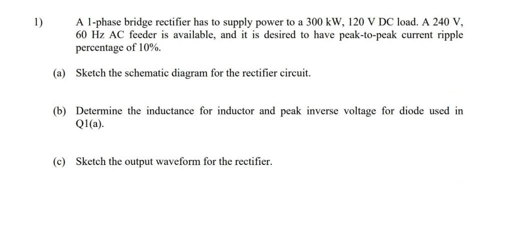
Transcribed Image Text:A l-phase bridge rectifier has to supply power to a 300 kW, 120 V DC load. A 240 V,
60 Hz AC feeder is available, and it is desired to have peak-to-peak current ripple
percentage of 10%.
1)
(a) Sketch the schematic diagram for the rectifier circuit.
(b) Determine the inductance for inductor and peak inverse voltage for diode used in
Q1(a).
(c) Sketch the output waveform for the rectifier.
Expert Solution
This question has been solved!
Explore an expertly crafted, step-by-step solution for a thorough understanding of key concepts.

Step by step
Solved in 2 steps with 2 images

Knowledge Booster


Learn more about
Need a deep-dive on the concept behind this application? Look no further. Learn more about this topic, electrical-engineering and related others by exploring similar questions and additional content below.Recommended textbooks for you
Delmar's Standard Textbook Of Electricity
Electrical Engineering
ISBN:
9781337900348
Author:
Stephen L. Herman
Publisher:
Cengage Learning
Delmar's Standard Textbook Of Electricity
Electrical Engineering
ISBN:
9781337900348
Author:
Stephen L. Herman
Publisher:
Cengage Learning