A question about 74LS04 IC (a Schmitt Trigger). The pictures show the 74LS04 logic, the connection required and data sheet. Question a)In order to light up the LED, what should Pin 1 and Point A connected to? Ans: Pin 1 connected to (5V / GND), Point A connected to (5V / GND). b)In this example, the power that lights up the LED comes from where? c)What is the current shown on the multi-meter? Is the current flowing out from Pin 2 or flowing into the Pin 2?
A question about 74LS04 IC (a Schmitt Trigger). The pictures show the 74LS04 logic, the connection required and data sheet. Question a)In order to light up the LED, what should Pin 1 and Point A connected to? Ans: Pin 1 connected to (5V / GND), Point A connected to (5V / GND). b)In this example, the power that lights up the LED comes from where? c)What is the current shown on the multi-meter? Is the current flowing out from Pin 2 or flowing into the Pin 2?

Electricity for Refrigeration, Heating, and Air Conditioning (MindTap Course List)
10th Edition
ISBN:9781337399128
Author:Russell E. Smith
Publisher:Russell E. Smith
Chapter17: Commercial And Industrial Air-conditioning Control Systems
Section: Chapter Questions
Problem 22RQ

Related questions
Question
100%
A question about 74LS04 IC (a Schmitt Trigger). The pictures show the 74LS04 logic, the connection required and data sheet.
Question
a)In order to light up the LED, what should Pin 1 and Point A connected to? Ans: Pin 1 connected to (5V / GND), Point A connected to (5V / GND).
b)In this example, the power that lights up the LED comes from where?
c)What is the current shown on the multi-meter? Is the current flowing out from Pin 2 or flowing into the Pin 2?
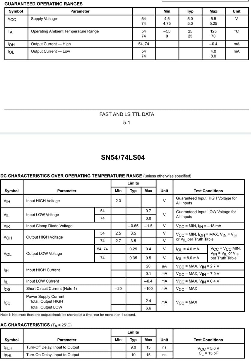
Transcribed Image Text:GUARANTEED OPERATING RANGES
Symbol
Parameter
Min
Тур
Мах
Unit
Vcc
Supply Voltage
54
4.5
5.0
5.5
V
74
4.75
5.0
5.25
TA
Operating Ambient Temperature Range
54
-55
25
125
°C
74
25
70
IOH
Output Current- High
54, 74
-0.4
mA
lOL
Output Current- Low
54
4.0
mA
74
8.0
FAST AND LS TTL DATA
5-1
SN54/74LS04
DC CHARACTERISTICS OVER OPERATING TEMPERATURE RANGE (unless otherwise specified)
Limits
Symbol
Parameter
Min
Тур
Маx
Unit
Test Conditions
Guaranteed Input HIGH Voltage for
All Inputs
VIH
Input HIGH Voltage
2.0
V
54
0.7
Guaranteed Input LOW Voltage for
VIL
Input LOW Voltage
V
All Inputs
74
0.8
VIK
Input Clamp Diode Voltage
|-0.65
-1.5
V
Vcc = MIN, IjN = -18 mA
54
2.5
3.5
V
Vcc = MIN, IOH = MAX, VIN = VIH
or VIL per Truth Table
VOH
Output HIGH Voltage
74
2.7
3.5
Vcc = Vcc MIN,
VIN = VIL or VIH
per Truth Table
54, 74
0.25
0.4
V
IOL = 4.0 mA
VOL
Output LOW Voltage
74
0.35
0.5
0.5
V
lOL = 8.0 mA
20
HA
Vcc = MAX, VIN = 2.7 V
IH
Input HIGH Current
0.1
mA
Vcc = MAX, VIN = 7.0 V
IL
Input LOW Current
-0.4
Vcc = MAX, VIN = 0.4 V
mA
los
Short Circuit Current (Note 1)
-20
-100
Vcc = MAX
Power Supply Current
Total, Output HIGH
2.4
Ic
Vcc = MAX
mA
Total, Output Low
6.6
Note 1: Not more than one output should be shorted at a time, nor for more than 1 second.
AC CHARACTERISTICS (TA = 25°C)
Limits
Symbol
Min
Тур
Max
Test Conditions
Parameter
Unit
tPLH
Turn-Off Delay, Input to Output
9.0
15
Vcc = 5.0 V
CL = 15 pF
ns
tPHL
Turn-On Delay, Input to Output
10
15
ns
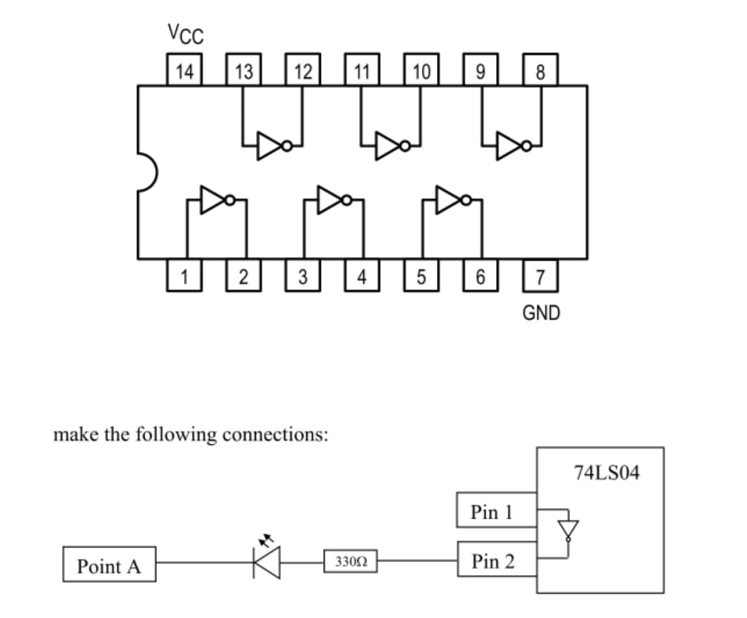
Transcribed Image Text:Vcc
14
13
12
11
10
9
8
3
4
5
6
GND
make the following connections:
74LS04
Pin 1
Point A
3302
Pin 2
Expert Solution
This question has been solved!
Explore an expertly crafted, step-by-step solution for a thorough understanding of key concepts.

Step by step
Solved in 3 steps with 4 images

Knowledge Booster


Learn more about
Need a deep-dive on the concept behind this application? Look no further. Learn more about this topic, electrical-engineering and related others by exploring similar questions and additional content below.Recommended textbooks for you
Electricity for Refrigeration, Heating, and Air C…
Mechanical Engineering
ISBN:
9781337399128
Author:
Russell E. Smith
Publisher:
Cengage Learning

Power System Analysis and Design (MindTap Course …
Electrical Engineering
ISBN:
9781305632134
Author:
J. Duncan Glover, Thomas Overbye, Mulukutla S. Sarma
Publisher:
Cengage Learning
Electricity for Refrigeration, Heating, and Air C…
Mechanical Engineering
ISBN:
9781337399128
Author:
Russell E. Smith
Publisher:
Cengage Learning
Power System Analysis and Design (MindTap Course …
Electrical Engineering
ISBN:
9781305632134
Author:
J. Duncan Glover, Thomas Overbye, Mulukutla S. Sarma
Publisher:
Cengage Learning