A simply supported beam is subjected to a 5 kN point load at B, a 3 kNm external moment at C and a 4 kN/m uniformly distributed load as shown in figure Q6. The beam is supported by a pin joint at A and a roller joint at D. Enter your solution on the answer sheet and show your working for the following questions: kN
A simply supported beam is subjected to a 5 kN point load at B, a 3 kNm external moment at C and a 4 kN/m uniformly distributed load as shown in figure Q6. The beam is supported by a pin joint at A and a roller joint at D. Enter your solution on the answer sheet and show your working for the following questions: kN

Mechanics of Materials (MindTap Course List)
9th Edition
ISBN:9781337093347
Author:Barry J. Goodno, James M. Gere
Publisher:Barry J. Goodno, James M. Gere
Chapter5: Stresses In Beams (basic Topics)
Section: Chapter Questions
Problem 5.8.11P: A wood beam AB on simple supports with span length equal to 10 ft is subjected to a uniform load of...

Related questions
Question
B1
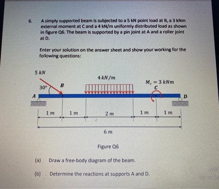
Transcribed Image Text:A simply supported beam is subjected to a 5 kN point load at B, a 3 kNm
external moment at Cand a 4 kN/m uniformly distributed load as shown
in figure Q6. The beam is supported by a pin joint at A and a roller joint
6.
at D.
Enter your solution on the answer sheet and show your working for the
following questions:
5 kN
4 kN /m
M. = 3 kNm
C
B
30°
A
D
1 m
1 m
2 m
1 m
1 m
6 m
Figure Q6
(a)
Draw a free-body diagram of the beam.
va
(b)
Determine the reactions at supports A and D.
Expert Solution
This question has been solved!
Explore an expertly crafted, step-by-step solution for a thorough understanding of key concepts.

Step by step
Solved in 2 steps with 2 images

Knowledge Booster


Learn more about
Need a deep-dive on the concept behind this application? Look no further. Learn more about this topic, mechanical-engineering and related others by exploring similar questions and additional content below.Recommended textbooks for you
Mechanics of Materials (MindTap Course List)
Mechanical Engineering
ISBN:
9781337093347
Author:
Barry J. Goodno, James M. Gere
Publisher:
Cengage Learning
Mechanics of Materials (MindTap Course List)
Mechanical Engineering
ISBN:
9781337093347
Author:
Barry J. Goodno, James M. Gere
Publisher:
Cengage Learning