A simply supported prismatic beam carries a concentrated downward load of 12 kN, as shown in the Figure, below. Determine the slope of the deflected shape at both reaction points, A and B, if the elastic modulus, E 210 GPa and the second moment of area, I- 10000 cm. 12 kN 2.0 m 3.0 m
A simply supported prismatic beam carries a concentrated downward load of 12 kN, as shown in the Figure, below. Determine the slope of the deflected shape at both reaction points, A and B, if the elastic modulus, E 210 GPa and the second moment of area, I- 10000 cm. 12 kN 2.0 m 3.0 m

Mechanics of Materials (MindTap Course List)
9th Edition
ISBN:9781337093347
Author:Barry J. Goodno, James M. Gere
Publisher:Barry J. Goodno, James M. Gere
Chapter9: Deflections Of Beams
Section: Chapter Questions
Problem 9.5.1P: A simply supported beam (E = 1600 ksi) is loaded by a triangular distributed load from A to C(see...

Related questions
Question
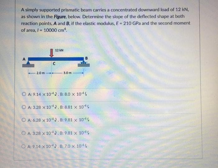
Transcribed Image Text:A simply supported prismatic beam carries a concentrated downward load of 12 kN,
as shown in the Figure, below. Determine the slope of the deflected shape at both
reaction points, A and B, if the elastic modulus, E= 210 GPa and the second moment
%3!
of area, I = 10000 cm.
12 kN
2.0 m +
3.0 m
O A: 9.14 x 1042, B: 8.0 x 10⁴
O A: 3.28 x 10², B: 8.81 x 10⁴
O A: 6.28 x 10². B: 9.81 x 10⁴
O A: 3.28 x 1042. B: 9.81 x 1040
O A: 9.14 x 1042. B: 7.0 x 10⁴
Expert Solution
This question has been solved!
Explore an expertly crafted, step-by-step solution for a thorough understanding of key concepts.

Step by step
Solved in 4 steps

Knowledge Booster


Learn more about
Need a deep-dive on the concept behind this application? Look no further. Learn more about this topic, mechanical-engineering and related others by exploring similar questions and additional content below.Recommended textbooks for you
Mechanics of Materials (MindTap Course List)
Mechanical Engineering
ISBN:
9781337093347
Author:
Barry J. Goodno, James M. Gere
Publisher:
Cengage Learning
Mechanics of Materials (MindTap Course List)
Mechanical Engineering
ISBN:
9781337093347
Author:
Barry J. Goodno, James M. Gere
Publisher:
Cengage Learning