From the double-end overhanging beam shown below, solve the reaction forces at the supports 19N 20N 7N 45m 2.5 m
From the double-end overhanging beam shown below, solve the reaction forces at the supports 19N 20N 7N 45m 2.5 m

Mechanics of Materials (MindTap Course List)
9th Edition
ISBN:9781337093347
Author:Barry J. Goodno, James M. Gere
Publisher:Barry J. Goodno, James M. Gere
Chapter6: Stresses In Beams (advanced Topics)
Section: Chapter Questions
Problem 6.10.17P

Related questions

Question
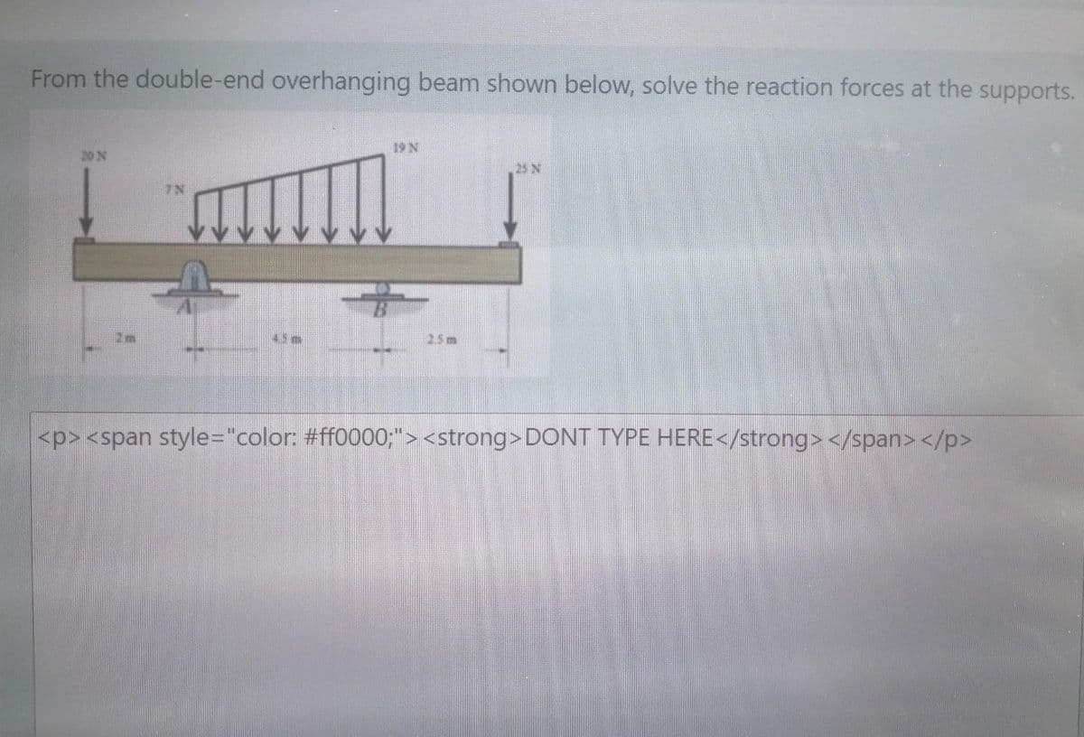
Transcribed Image Text:From the double-end overhanging beam shown below, solve the reaction forces at the supports.
19 N
20 N
25 N
7N
25m
<p><span style="color: #ff0000;"> <strong>DONT TYPE HERE</strong> </span> </p>
Expert Solution
This question has been solved!
Explore an expertly crafted, step-by-step solution for a thorough understanding of key concepts.

This is a popular solution!

Trending now
This is a popular solution!

Step by step
Solved in 2 steps

Knowledge Booster


Learn more about
Need a deep-dive on the concept behind this application? Look no further. Learn more about this topic, mechanical-engineering and related others by exploring similar questions and additional content below.Recommended textbooks for you
Mechanics of Materials (MindTap Course List)
Mechanical Engineering
ISBN:
9781337093347
Author:
Barry J. Goodno, James M. Gere
Publisher:
Cengage Learning
Mechanics of Materials (MindTap Course List)
Mechanical Engineering
ISBN:
9781337093347
Author:
Barry J. Goodno, James M. Gere
Publisher:
Cengage Learning