A steel rod of diameter 15 mm is held (without any initial stresses) between rigid walls by the arrangement shown in the Figure. Calculate the temperature drop AT (degrees Celsius) at which the average shear stress in the 12-mm diameter bolt becomes 45 MPa. (For the steel rod, use a=12x10/°C and E=200 GPa.) 12 mm diameter bolt 15 mm
A steel rod of diameter 15 mm is held (without any initial stresses) between rigid walls by the arrangement shown in the Figure. Calculate the temperature drop AT (degrees Celsius) at which the average shear stress in the 12-mm diameter bolt becomes 45 MPa. (For the steel rod, use a=12x10/°C and E=200 GPa.) 12 mm diameter bolt 15 mm

Mechanics of Materials (MindTap Course List)
9th Edition
ISBN:9781337093347
Author:Barry J. Goodno, James M. Gere
Publisher:Barry J. Goodno, James M. Gere
Chapter2: Axially Loaded Members
Section: Chapter Questions
Problem 2.6.5P

Related questions

Question
None
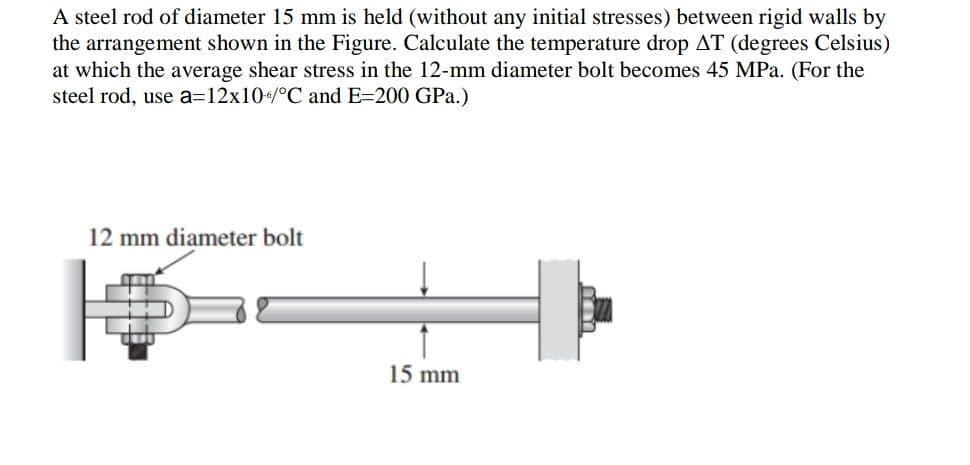
Transcribed Image Text:A steel rod of diameter 15 mm is held (without any initial stresses) between rigid walls by
the arrangement shown in the Figure. Calculate the temperature drop AT (degrees Celsius)
at which the average shear stress in the 12-mm diameter bolt becomes 45 MPa. (For the
steel rod, use a=12x10/°C and E=200 GPa.)
12 mm diameter bolt
15 mm
Expert Solution
This question has been solved!
Explore an expertly crafted, step-by-step solution for a thorough understanding of key concepts.

This is a popular solution!

Trending now
This is a popular solution!

Step by step
Solved in 3 steps

Knowledge Booster


Learn more about
Need a deep-dive on the concept behind this application? Look no further. Learn more about this topic, mechanical-engineering and related others by exploring similar questions and additional content below.Recommended textbooks for you
Mechanics of Materials (MindTap Course List)
Mechanical Engineering
ISBN:
9781337093347
Author:
Barry J. Goodno, James M. Gere
Publisher:
Cengage Learning
Mechanics of Materials (MindTap Course List)
Mechanical Engineering
ISBN:
9781337093347
Author:
Barry J. Goodno, James M. Gere
Publisher:
Cengage Learning