)A symmetrical delta-connected 415V three-phase supply is feed to an asymmetrical delta- connected load as shown in Figure Q2(b). Assume that it is a RYB sequence. The impedances of the load are ZRY = 50 + j50 2, ZYB = 150 + jo 2 and ZBR = 50 –js0 2. (i) Determine and draw the phasor diagram of phase currents in the load. (ii) Determine and draw the phasor diagram of line currents in the system.
Q: Suppose two generators supplying a load. Generator-1 has a no-load frequency of 61.5 Hz and a slope…
A: The resulting power frequency diagram is shown below
Q: What are the typical power quality issues in the power system? What are the methods to mitigate…
A: The typical power quality issues in the power system are: Over voltage: Over voltage power increase…
Q: Q3. The load impedance in the circuit shown in Figure 2 is shunted by a capacitor having a…
A:
Q: 1.Thyristor-Switched Series Reactor (TSSR) for power factor improvement
A: NOTE: As per the policy, I can only answer one question at a time. Please ask the second question…
Q: Question No. 1: Figure below gives the general D-Y transformation, (a) Show that the general…
A: The general transformation reduces to as given in figure for a balanced three phase loadFor ∆-…
Q: A- A3-ph, double circuit O.H.T.L, 320 kV, 340 km, 50 Hz has a configuration as shown in the figure…
A: “Since you have posted a question with multiple sub-parts, we will solve first three subparts for…
Q: Q4/ /A/ A 3-phase, Shp, 208V, 4-pole, 60H IMbjected to no load test at 60HZ and short circuit at…
A:
Q: PRELIMINARY QUESTIONS: 1) What is the phase angle between the phases in an ideal 3-phase system?
A: Bartleby has policy to solve only first question. For rest questions re-upload them only.
Q: Q4: A power distribution station consisting of 100OKVA, 4500V/225V, and 50 cycles per second…
A: Write the expression for the number of turns,
Q: Consider a 3-phase delta induction motor that is operating at 120 Hz. The motor (load) impedance,…
A: Hello. Since your question has multiple sub-parts, we will solve first three sub-parts for you. If…
Q: explain the operating principle of single phase 2S-2P PMSM based on 3D design illustration.
A: According to the question, explain the operating principle of single-phase 2S-2P PMSM based on 3D…
Q: (b) Figure Q2 shows a power system network. The generators at Bus 1 and Bus 2 are represented by…
A: Given: Figure below shows the power system network: The generators at Bus 1 and Bus 2 are…
Q: 3. A three-phase 60 Hz Wye connected, 2,000-kVA, 2,300-V alternator give a short circuit-test…
A: The solution is given below
Q: Q2/| answer true or false and correct the false ;if any. 1- The purpose of load test the single…
A: Electrical machines can be either generator , motors or transformers . They can be either Ac…
Q: A step-down chopper, with voltage source 20V. If the duty cycle is 50% and chop frequency is 0.1Hz,…
A: In this question , step down chopper is given...We have to find out ON time of chopper and average…
Q: (b) Figure Q2 shows a power system network. The generators at Bus 1 and Bus 2 are represented by…
A: i) Admittance network of the given system
Q: An existing dc three wire system is to be converted into a 3phase 4 wire system by adding a fourth…
A: Same supply and load voltages, balanced condition and unity power factor 1) DC three wire system…
Q: Three-phase alternator supplying a three wires, CBA system with a line voltage of 100 Volt,…
A:
Q: Is it possible to measure the phase-shift angle in an AC single-phase circuit by an indirect method…
A: The electrical circuits have resistance, inductance and capacitance as their elements. In the…
Q: Q2) The two control areas are interconnected through a tie-line. The parameters of each area based…
A: Two different areas are connected through tie line, to support one another to maintain constant…
Q: Q2// Explain the terms, connocted load, load factor, plant use fnctor, divervity factor.
A: In this question, We need to Explain the terms of connected load, load factor, plant use factor and…
Q: 6. Explain following with examples and diagrams. a. Load curve b. Plant capacity factor c. Mean time…
A:
Q: A step-down chopper, with voltage source 20V. If the duty cycle is 50 frequency is 0.1Hz, Find…
A:
Q: = Two 1-ph transformers 6000/400V, the first 200kVA and the other is 350kVA when performing the…
A: TRANSFORMER : A transformer is a passive electrical device that transmits electrical energy from…
Q: What can you say about the flow of power as a function of time between a balanced three-phase source…
A: Concept: A definition of a function is that a relation from a set of inputs to a set of possible…
Q: 
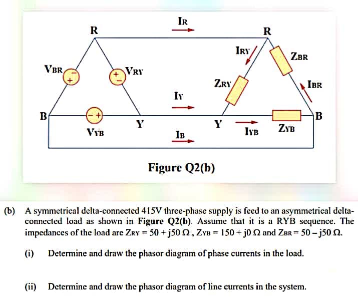
(b) A symmetrical delta-connected 415V three-phase supply is feed to an asymmetrical delta-…
A:
Q: We use two identical transformers in experiment: (Parallel operation of two transformers) to achieve…
A: In order to achieve the condition of parallel operations of two transformers the given below…
Q: are complex power demands at bus-1 and bus-2 For the system shown in figure, Sp, and SD,…
A: we need to find out VAR rating of capacitor QG2 at bus-2 in MVAr.
Q: What are symmetrical components and why are they used
A: Characteristic of three phase balanced system: Each phase is displaced by 120° phase angle. Each…
Q: For type-A chopper of. dc source voltoge = 230 V, load resistance = 102. Take a voltage drop of 2 V…
A: Given values are - VS=230VVD=2VDuty ratioD=0.4 Given that chopper is type-A so that it is step down…
Q: 1. Thyristor-Controlled Series Capacitor (TCSC) for power factor improvement 2. What are the…
A: Thyristor -Controlled Series Capacitor (TCSC) TCSC is a series compensation device connected to the…
Q: 5.5 kW, 1450 rpm. L-type equivalent circuit and parameters for a continuous sinusoidal phase of a…
A: Given: 5.5 kW, 1450 rpm, line voltage 220 V and frequency 50 Hz. R1=0.21Ω, R2=0.18Ω,…
Q: Sketch the complete per-phase equivalent circuit of a symmetrical non-salient pole three-phase…
A: Synchronous generator: It is an electromechanical device. This is called a synchronous generator…
Q: A 3Ø, Y-connected alternator is rated at 1,600KVA, 13.5KV. The armature effective AC resistance per…
A: Three phase star connection connected to common point or neutral point. Three phase star connection…
Q: State True or false a- The DC load flow study is a linear analysis b- In a load frequency control, a…
A: a ) True In DC power flow analysis no reactive power , inductor, capacitor are present hence it is…
Q: A balanced A-connected load consisting of a pure resistances of 152 per phase is in parallel with a…
A: Explanation: a) Converting the delta circuit into an equivalent star circuit, so the per branch…
Q: A) Highlight two significances of power factor correction.
A: We are authorized to answer one question at a time, since you have not mentioned which question you…
Q: UDng a ITIe Core in high frequency transformers. c- Discuss, different applications of iron cores of…
A: C)For magnetizing or demagnetizing a iron material, some energy is expended. The energy expended…
Q: Two impedances are supplied by Vrms, as shown in Figure 2, where Arms. The first load draws P₁ =…
A: It is given that: P1=23.2 WQ1=50 VARAssuming,V=100∠160° VI=2∠190° A
Q: Is it true??
A: For the transmission of the equal power to three loads impedance will need only the half of the…
Q: Questions:- 1. Identify unity power factor points on V-curves and comment why you will not get unity…
A: 1) V bend is a plot of the stator current versus field current for various consistent burdens. The…
Q: A three-phase system has balanced conditions so that the per-phase circuit representation can be…
A: The three-phase system diagram is shown below, Here,The load voltage is,VL=4kVrmsThe load impedance…
Q: in distribution transformers; What is 30 degrees phase shift in delta-star connection? What are the…
A: In the star-delta connection, the primary side of the transformer is in delta configuration while…
Q: To qualify system stability, we use: a. Routh criterion b. Phase margin c. Gain and phase margin d.…
A: We use Routh–Hurwitz stability criterion as a System Stability
Q: The following figure represents a simplified model of the power supply to a load centre from a…
A: Consider the base power is 500 MVA and the base voltage on the LV side of the transformer is 13.8 kV…
Q: 8- What do you understand from the load curve and what information are converged by a load curve.
A: The following are the information obtained from load curves. 1. Load duration curve determines the…
Q: L-type equivalent circuit and parameters for a continuous sinusoidal phase of a 5.5 kW, 1460 rpm,…
A:
Q: a) Write the Biot-Savart Law for a steady current I.
A: “Since you have asked multiple question, we will solve the first question for you. If you want any…
Step by step
Solved in 2 steps with 1 images
- An AC three phase distribution system (given in Figure 2), which has end user with balanced three phase (10A) load, is given in the figure. The phase-neutral voltages of the transformers are given as V1=224V, V2=225V, V3=228V and V4=231V respectively. a) Calculate phase-neutral voltage of the bus-bar (B). b) Calculate currents of the transformers (I1, I2, I3 and I4) c) Calculate phase-neutral voltage of the point K while the output of TR3 and TR4 (xy) have been short circuited for a transient time (transformers are still operational) by the line fault.Problem 2: A single-phase transformer of turn ratio (2:1), R1=0.72, X-2.52, R2-0.32, X2-1.52. The no-load current I,=10A leading the flux () by 64°. If the primary draws 45A at voltage is 500V and unity power factor. Determine by aid of a vector diagram: 1. Load voltage, 2. Load current, 3. Load power factor, 4. Load impedance, 5. Iron and copper losses, 6. Efficiency, 7. The percentage factor for maximum efficiency, 8. The magnetizing circuit resistance R., inductanceWhich termination would result to a phase change of 180 degrees at the load if Zo = 100 ohm? a. 50 ohm b. short circuit c. 75 ohm d. all of these What is the purpose of impedance matching? a. maximum return loss b. maximum SWR c. maximum load power d. maximum reflection A short piece of transmission line that may be open or shorted and used for impedance matching purposes. a. converter b. decoder c. stub d. transformer
- Electric Machine; Check image, all question there. Consider the above approximate equivalent circuit for IM. A six-pole, 220Volt (line to line), 50Hz, Y connected, three phase IM has the following on a per phase basis: R1=0.5Ω , R2=0.25 Ω, X1=0.75 Ω, X2=0.5 Ω, Xm=100 Ω, Rc=500 Ω The friction and windage loss is 150 W. Determine the following at its rated slip of 3.5% a)Total Impedance(Zt) b)Rotor Copper Loss c)Core loss(Pm) d)Shaft Power(P0) e)EfficiencyShown are two buses connected via a transmission line. Connected to Bus 1 is a generator(modelled as a voltage source V1), and to Bus 2 is a generator( with Voltage V2) and a load. The line impedance Z = R + jX is not known. Three-phase load is forecasted as 100MW + 60MVar. Generator at Bus 2 is scheduled to deliver 40MW and its excitation is adjusted for the machine to deliver 55 MVar. Voltage at Bus 1 is 241 KV angle 10 deg, while voltage at bus is 230 kV; use V2 as the reference for all angles. 1. What is the current (RMS) in amperes drawn by the load connected to Bus 2? 2. How much real power (in MW) is delivered by the generator connected to Bus 1? 3. What is the total real power loss along the line, in percent of the load? 4. What is the X/R Ratio of the line impedance?Consider a 10 kVA, 200/400 V, 50 HZ: single-phase tranformer has the folloving test results:0.C. test: 200 V, 0.6A, 63 W (L.V.side)S.C. test : 20 V, 25A, 85 W (H.V. side)Deternine:i- The eficiengy at 75 % offiull-load at 0.9 leading power factor.ii -The secondary terminal voltage on fill-load at tunity power facton
- Suppose two generators supplying a load. Generator-1 has a no-load frequency of 61.5 Hz and a slopesp1 of 1 MW/Hz. Generator-2 has a no-load frequency of 62 Hz and a slope sp2 of 1MW/Hz. The twogenerators are supplying a real load totaling 2.5 MW at 0.8 PF lagging. Draw the resulting systempower-frequency or house-diagrams. Determine (a) at what frequency is the system operating, andhow much power is supplied by each of the generators? (b) if an additional 0.75-MW load wereattached to this power system. What would the new system frequency be, and how much powerwould the each generator supply now? (c) with the system in the configuration described in part (b),what will the system frequency and generators power be if the governor set points on generator-1 areincreased by 0.5 Hz?A star connected load with real impedance ZL= 1-j1 Ohm per phase is connected to the secondary of a three-phase Ynyn0 connected transformer. The equivalent impedance per reduced phase of the transformer to the primary is Zeq1= 1+j5 Ohm. The nominal primary voltage is V1Ln= 5920 V and the conversion ratio is a= 10. what is the amplitude of the actual voltage falling on one phase of the specified load? (simplified equivalent circuit will be used).A three-phase system has balanced conditions so that the per-phase circuit representation can be used as shown in Figure 1 Select the turns ratio of the step-up and step-down transformers that the system operates with an efficiency greater than 99 percent. Moreover, find the complex power (received or given) of all components in the circuit and the V1 and V2 voltages. The load voltage is specified as 4 kV rms, and the load impedance is 4/3 ohm. ..
- What can you say about the flow of power as a function of time between a balanced three-phase source and a balanced load? Is this true of a single-phase source and a load? How is this a potential advantage for the three-phase system? What is another advantage of threephase power distribution compared with single-phase?A circuit feeding a single-phase load of 2.75 kW at 0.85 power factor and 240 V at an ambient temperature of 55°C by means of a 27 m single-core PVC insulated cable run in conduit along with another circuit. 1) Determine the installation method 2) Compute the circuit design current (/g) 3) Determine the nominal current (Za) of the circuit breaker 4) Find the temperature correction factor (C;) and adjust current for temperature 5) Find the grouping correction factor (Cy) and adjust current for grouping of cables 6) Select cable size and determine its current carrying capacity (/z) 7) Check voltage drop (V.D.) and correct cable size if V.D. > 6 V3) A 120 KVA three -phase transformer (three -phase power), 13200/480 V (line a line) in delta-strella connection has a resistance of 1.3% and a reactance of 8.2% per unit. a) Calculate the phase impedance of the transformer referred to the bass side voltage. b) Calculate the phase impedance of the transformer referred to the high side voltage. c) Calculate the efficiency of the transformer into nominal conditions and with F.P. 0.8 in delay. Three -phase loss in the nucleus is 1500 W.