A water jet washing system for galvanized steel profiles uses a series of n = 15 nozzles mounted on a segment of pipe as shown in the figure. Considering incompressible flow (compressed air with p=1.112 kg/m3) and a constant and equal flow rate in each nozzle, obtain for the case of a larger internal diameter D = 12.6 mm and the ratio of areas indicated in the figure, the following parameters: a) The total flow demanded from the compressor if a discharge velocity of not less than U2 = 25 m/s is required. b) The gauge pressure required in section 1 considering that the losses between that point and the discharge are equivalent in total to dP = 27.5 kPa. c) The resulting state of loads (forces and bending moment) on the flange, which is located at an effective lever arm of d = 68 mm from the axial symmetry axis of the nozzle.


Heat Exchangers
Heat exchangers are the types of equipment that are primarily employed to transfer the thermal energy from one fluid to another, provided that one of the fluids should be at a higher thermal energy content than the other fluid.
Heat Exchanger
The heat exchanger is a combination of two words ''Heat'' and ''Exchanger''. It is a mechanical device that is used to exchange heat energy between two fluids.
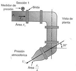
A water jet washing system for galvanized steel profiles uses a series of n = 15 nozzles mounted on a segment of pipe as shown in the figure. Considering incompressible flow (compressed air with p=1.112 kg/m3) and a constant and equal flow rate in each nozzle, obtain for the case of a larger internal diameter D = 12.6 mm and the ratio of areas indicated in the figure, the following parameters:
a) The total flow demanded from the compressor if a discharge velocity of not less than U2 = 25 m/s is required.
b) The gauge pressure required in section 1 considering that the losses between that point and the discharge are equivalent in total to dP = 27.5 kPa.
c) The resulting state of loads (forces and bending moment) on the flange, which is located at an effective lever arm of d = 68 mm from the axial symmetry axis of the nozzle.

Step by step
Solved in 2 steps with 1 images


