a. 
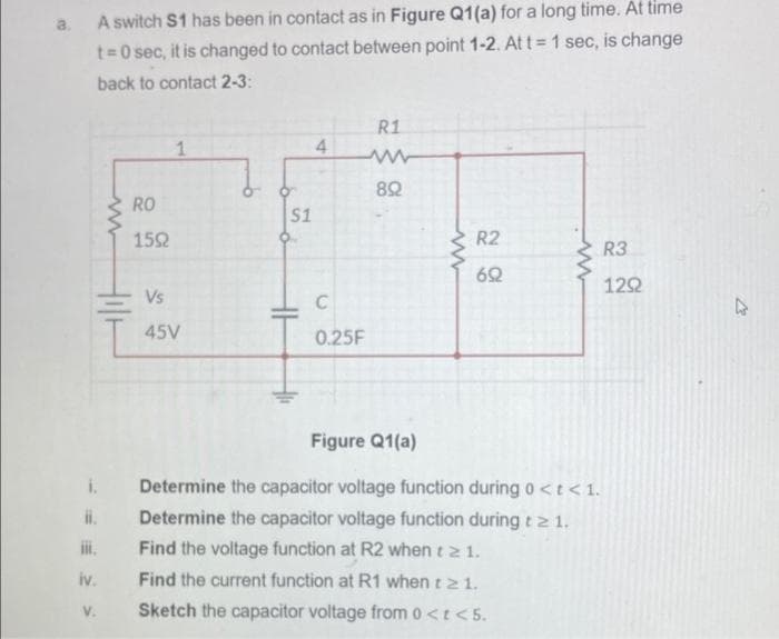
A switch S1 has been in contact as in Figure Q1(a) for a long time. At time t=0 sec, it is changed to contact between point 1-2. At t 1 sec, is change back to contact 2-3: R1 4 RO S1 152 R2 R3 62 122 Vs 45V 0.25F Figure Q1(a) i. Determine the capacitor voltage function during0
Q: 4) A long solenoid has n=800 turns per meter and a current I = 2 sin(wt). Inside the solenoid with…
A: According to guidelines we need to solve only the first three sub-parts. According to the question…
Q: Capacitors – if V1(t) is at the vdd potential (large and positive) at t = 0, derive an equation for…
A: Solution- The given circuit diagram is shown below,
Q: (b) The switch in the DC circuit of Figure 2(b) has been in position a for a long time. At time t =…
A: Brief description: Transient analysis is only applicable for those networks where network consists…
Q: A PV module has been tested using a steady-state solar simulator, and the following I-V and P-V…
A: To extract the maximum power from the PV, there are multiple MPPT controllers are used nowadays P…
Q: The switch in the circuit hasbeen in position a for a long time. At t=0, it moves instantaneously…
A: The circuit diagram is shown below: When the switch is at position a, the capacitor can be replaced…
Q: 1. In a circuit with impressed voltage e(t) and inductance L, Kirchhoff's first law gives the…
A:
Q: The switch, which is in (a) position for a long time, is brought to (b) position at time t = 0.…
A:
Q: Consider the R-C circuit. we idealise the emf to be constant and have zero internal resistance. We…
A: as stated, the capacitor is initially not charged. and it is conneced in series with the resistance…
Q: R1 = 82 SW1 + 18V C = 1/6F R2 = 122
A: Hello. Since your question has multiple sub-parts, we will solve the first three sub-parts for you.…
Q: R2 S2 4Ω ww R1 C1 C2 R3 R4 voct): 4F 32 4 A 6Ω 20 V Figure P5.41 .42 For the circuit shown in Figure…
A: Note: We are authorized to answer three subparts at a time since you have not mentioned which part…
Q: onsider the circuit shown below. The switch has been in position a for a ng time. The capacitor is…
A:
Q: lle = 2+ (5 – 2)e-15t = 2+ 3e-15t A, %3D t > 0 %3D Example At t= 0, switch 1 is closed, and switch 2…
A:
Q: In the RL circuit shown below, the switch is open for a long time and closes at t = 0. If Is =…
A:
Q: Q2/ For the network shown in figure (Q2), the switch has been open for a long time before closing at…
A:
Q: The circuit shown in Figure P3.72 has i L ( t )= 0.1 cos( 5000t ) A in which the argumentof the cos…
A: Write the expression for the voltage across the inductor and substitute the known values.
Q: An inductor (L= 0.35 H) and two resistors (R1 = R2 = 2.0 N) are connected to a battery with an emf…
A: According to question: a) The potential drop across inductor at t=0.040sec is calculated as…
Q: Q1/ For the networks shown in Figures (Q1), the switch has been at position "A" for a long time. At…
A:
Q: We begin the problem with an open switch and an uncharged capacitor. At time t = 0, the switch is…
A: R1=32 Ω, R2=21 Ω, R3=74 Ω, R4=87 Ω, C=46 μF, Vbat=20 V. The switch S is closed at a time t=0 second.
Q: 2. The equation of electric charge on the capacitor is related to the equation of current strength…
A: Given the differential equation in RLC circuit as : Ld2qdt2+Rdqdt+1Cq=E(t) Given: R=10 Ω, L=0.25 H,…
Q: (a) For the circuit shown in Figure 3.1, what is the time constant, r? t=0 10 ko 3 kN 3 μ 10 V…
A:
Q: a) Write the mathematical expressions for ve, VRi, and ic after the switch is thrown into position…
A: The switch is thrown to position '1' at a time t=0 s as shown in the figure below.
Q: 3. For the R-C circuit in below figure, composed of standard values: a. Determine the time constant…
A: As per company guidelines we can solve only first three sub parts kindly post another parts…
Q: Vind Figure 1 Consider two infinitely long wires carrying currents I and I, cross (without…
A:
Q: Consider the circuit shown in the figure, with ε=36.0V,R0=50.0Ω,R=150Ω andL=4.00H. (a) Switch S1 is…
A:
Q: The switch shown in Figure Q2 has been open for a long time, and the initial charge on the capacitor…
A: The circuit is: for t<0. the circuit is: The voltage across the capacitor initially = 0 Vc0-=0…
Q: Assume the capacitor to be fully discharged before the switch closes to position 1 at t=0: A.…
A: The circuit is given as The value of resistance is given as R1=2kΩR2=5kΩC=25μF
Q: Q1 of 2) The circuit given has reached steady state before the switch closes at time t = 0. (a)…
A:
Q: The starting voltage of the C = 0.05 microfarad capacitor given in the figure is V0 = 30 Volts and…
A:
Q: Due to components not shown in the figure, the circuit of Figure P4.41 has i L ( 0 )= I i . a. Write…
A: The circuit can be modified as applying KVL to the given circuit
Q: Q K A Square parallel plate capacitor with side length l= 50cm and thickness d = 1mm, has charge Q =…
A:
Q: 4. For the circuit shown below, let C = 0.25 F, R1 = R2 = 4 ohms, and V = 20 V. If the current in R2…
A:
Q: An inductor of 2 henrys, a resistor of 16 ohms and a capacitor of 0.02 farads are connected in…
A: Given that a series circuit consists of L=2H, R=16 ohm, C=0.02 F, and emf E=300 V. All initial…
Q: A circuit has in series of electromotive force given by E(t) = 100 sin 60t V, a resistor of 2 Ω, an…
A: It is given that: Et=100sin60t Vr=2 ΩL=0.1 HC=1260 Fi0-=0=dq0-dt=q'0-=0 Aq0-=0 C
Q: Determine expressions for and sketch v R ( t ) to scale versus time for the circuit of Figure P4.43.…
A: Concept: The circuit which is used to electrically describe and model either continuous materials or…
Q: Suppose that a parallel-plate capacitor has a dielectric that breaks down if the electric field…
A: Concept: A passive two-terminal electrical component used to store energy electrostatically in an…
Q: From Figure Q2(c), calculate the time domain steady state expression for v, i,, and iz when i, = 10…
A:
Q: Determine the current i1Ohm(t) for t > 0 (assume steady state at t = 0-). b. Plot i1Ohm(t) vs. t…
A: Given the circuit, as shown below: a) We need to determine the current i1Ohm(t) for t > 0…
Q: The current through a 3-μF capacitor is shown in Figure P3.14. At t = 0, the voltage is v(0) = 10 V.…
A: Write the expression for the voltage across the capacitor for 0 < t < 1ms.…
Q: Q1/ For the network shown in figure (Q1), the switch has been in position "a" for a long time. At…
A: To find current through the inductor , first we need to know that , under steady state condition ,…
Q: QI/ For the network shown in figure (Q1), the switch has been in position "a" for a long time. At…
A: In the above circuit the switch was at position for 'a' for long time. Converting the 5,12,8 ohm…
Q: The circuit shown in Figure-2 is at steady state before the switch closes at time t = 0. The input…
A:
Q: In the circuit shown in the figure, switch S is closed at t = 0. a) What is the current in the…
A: Inductor: It is a passive two-terminal electrical component and measured in Henry (H). When…
Q: FACULTY OF SCIENCES DEPARTMENT OF PHYSICS QUESTION NO. 2: MANDATORY/DOPTIONAL / BONUS In the figure,…
A: Given- C =0.4 uF ε= 20 V R1 = 10 k ohm R2= 15 k ohm
Q: A circuit with a battery, 2 resistors, a capacitor, and a switch is built as shown in the figure.…
A:
Q: Q1/ For the network shown in figure (Q1), the switch has been in position "a" for a long time. At…
A: For the network, the switch at position a. For. Long time. At time t= 0, the switch moves position…
Q: 3. The switch in figure-2 changes at t= 0 from ground to the source given by v, (). Determine: (a)…
A: When t<0: The output is connected to ground. Therefore, output is zero. V0(t)=0V. When t>0:…
Q: A sphere of radius r floats in water. The volume of a spherical segment is (3 rh² – h° ). Find the…
A: The given data's are, A sphere of density is 800 kg/m2, The volume of spherical segment is, π33…
Q: b SHOW un c What value does the levěl III lIMU d. The level in the right compartment has risen 6cm…
A:
Q: As shown, the battery has emf ε = 18.0 V and the other circuit elements have values L = 0.400 H, R1…
A: NOTE_ “Since you have posted a question with multiple sub-parts, we will solve first three subparts…
Q: (a) In Figure Q.3(a), the switch has been in position "a" for a long time, and it is switched to "b"…
A: We know behaviour of capacitor at t = 0 , and we also know the behaviour of capacitor as t tends to…
Step by step
Solved in 5 steps with 5 images
- Consider the circuit shown in Figure P14.44. The two coils have L1=0.1 H, L2=10 H, and M=1 H. Prior to t=0, the currents in the coils are zero. At t=0, the switch closes. Determine and sketch i1(t) and v2(t) to scale versus timeA current waveform in Figure Q1(a)(i) is applied to the circuit input, is, inFigure Q1(a)(ii). Assuming that the capacitors are initially uncharged, find theoutput voltage, ??(?).a series circuit contains a resistor and an inductor as shown in figure 1.3.14. determine a differential equation for the current i (t) if the resistance is R, the inductance is L, and the impressed voltage is E(t)
- For the circuit shown in Figure P1.76, solve for i s. What types of sources are present in this circuit?Q-1: Give brief answer to the following: (Answer Ten only)1) what is the potential transformer used for in power substation?2) what is process leads to lowering the number of free electrons?3) what is The Townsend’s Criterion4) why Sulphur Hexafluorid has good insulation strength?5) What is Intrinsic Breakdown6) why do bubbles lead to breakdown of liquid?7) how to decease the ripple voltage of cockroft-walton voltage multiplier circuit8) how much the maximum charging current of A Van de Graaff generator has a beltwidth 1 m, a belt speed of 4 m/s, and charge density of 10 c/m29) Why does need for Reactive Power Compensation in test transformer?10) The output voltage of series resonant circuit is given by the formula _________11) what is impulse voltage and what is its standard wave shape?12) Which advice can measure impulse voltage?5. Suppose we go around the loop counterclockwise, starting from point a and return to the starting point, what happens to the total electric potential? 6. As we go around the loop counterclockwise measuring potential differences across the circuit elements as we go. Use (+) sign for a potential increase and (-) for a potential drop. Write am equation for the travel we traced.
- A circuit powered by a 20V DC supply has a 50kΩ resistor and 20 μ Capacitor connected in series. For this circuit determine the:a. Initial value of the current flowing? b. The time constant of the circuit? c. The value of current after 1 second of connection? d. The value of capacitor voltage 2 seconds after the connection?Provide 3 sample calculations involving DC circuit under transient current condition on series R-L and Series R-C circuit? Need a simple supplementary explanation, can't quite understand the definitions I have currently.4_ For the system shown in figure N°4, find the percentage overshoot, the settling time, the peak time and the rising time for a unit step input if the response is underdamped. Is it muffled? Say why? Construct the graph of the answer c(t).
- Considering that the power loss of a resistor is RI^2 and the information in the manual’s background section, derive an expression for the energy lost through Joule heating in a resistor when a capacitor completely discharges.Solve for the currents shown in Figure P1.69.The circuit shown in the given figure is a model of a solenoid, such as that used to engage the gear of a car’s starter motor to the engine’s flywheel. The solenoid is constructed by winding a wire around an iron core to make an electromagnet. The resistance R is that of the wire, and the inductance L is due to the electromagnetic effect. When the supply voltage vs is turned on, the resulting current activates the magnet, which moves the starter gear. Obtain the model of the current i given the supply voltage vs.