(a). Write the instantaneous currents across the three circuit elements in terms of Vm amp > angular frequency @, inductance L, and capacitance C. (b). Relate for the ratio of the rms voltage and current towards the ratio of the amplitude voltage and current. (c). By using part (a) and (b), as well as the phasor diagram as guides, show that the rms current delivered by the source is 1 I =V. R? rms ms @L
(a). Write the instantaneous currents across the three circuit elements in terms of Vm amp > angular frequency @, inductance L, and capacitance C. (b). Relate for the ratio of the rms voltage and current towards the ratio of the amplitude voltage and current. (c). By using part (a) and (b), as well as the phasor diagram as guides, show that the rms current delivered by the source is 1 I =V. R? rms ms @L

Power System Analysis and Design (MindTap Course List)
6th Edition
ISBN:9781305632134
Author:J. Duncan Glover, Thomas Overbye, Mulukutla S. Sarma
Publisher:J. Duncan Glover, Thomas Overbye, Mulukutla S. Sarma
Chapter6: Power Flows
Section: Chapter Questions
Problem 6.61P

Related questions
Question
please show steps-by-steps solutions tq
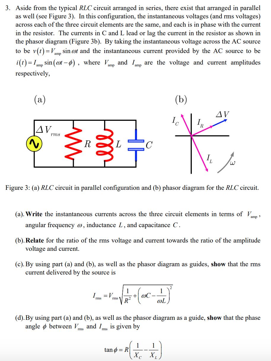
Transcribed Image Text:3. Aside from the typical RLC circuit arranged in series, there exist that arranged in parallel
as well (see Figure 3). In this configuration, the instantaneous voltages (and rms voltages)
across each of the three circuit elements are the same, and each is in phase with the current
in the resistor. The currents in C and L lead or lag the current in the resistor as shown in
the phasor diagram (Figure 3b). By taking the instantaneous voltage across the AC source
sin ot and the instantaneous current provided by the AC source to be
to be v(t)=V,
amp
i(t) = 1mp sin (ot – ø) , where Vmp and Imp are the voltage and current amplitudes
%3D
amp
respectively,
(a)
(b)
AV
Ic
R.
|AV.
rms
R
Figure 3: (a) RLC circuit in parallel configuration and (b) phasor diagram for the RLC circuit.
(a). Write the instantaneous currents across the three circuit elements in terms ofV.
amp >
angular frequency @, inductance L, and capacitance C.
(b). Relate for the ratio of the rms voltage and current towards the ratio of the amplitude
voltage and current.
(c). By using part (a) and (b), as well as the phasor diagram as guides, show that the rms
current delivered by the source is
1
+| @C•
R?
1
I.
= V
rms 1
rms
@L
(d). By using part (a) and (b), as well as the phasor diagram as a guide, show that the phase
angle ø between V.
and Ims is given by
rms
1
tan ø = R|
1
Xc X,
Expert Solution
This question has been solved!
Explore an expertly crafted, step-by-step solution for a thorough understanding of key concepts.

This is a popular solution!

Trending now
This is a popular solution!

Step by step
Solved in 4 steps with 9 images

Knowledge Booster


Learn more about
Need a deep-dive on the concept behind this application? Look no further. Learn more about this topic, electrical-engineering and related others by exploring similar questions and additional content below.Recommended textbooks for you
Power System Analysis and Design (MindTap Course …
Electrical Engineering
ISBN:
9781305632134
Author:
J. Duncan Glover, Thomas Overbye, Mulukutla S. Sarma
Publisher:
Cengage Learning
Power System Analysis and Design (MindTap Course …
Electrical Engineering
ISBN:
9781305632134
Author:
J. Duncan Glover, Thomas Overbye, Mulukutla S. Sarma
Publisher:
Cengage Learning